2013 SUBARU TRIBECA towing
[x] Cancel search: towingPage 320 of 420

&Towing and tie-down hooks
The towing hooks should be used only in
an emergency (e.g., to free a stuck vehicle
from mud, sand or snow).
CAUTION
. Use only the specified towing
hooks and tie-down hooks. Never
use suspension parts or other
parts of the body for towing or
tie-down purposes.
. Never use the tie-down hook
closest to the muffler under the
vehicle for towing purposes.
. To prevent deformation to the
bumper and the towing hook, do
not apply excessive lateral load
to the towing hooks.
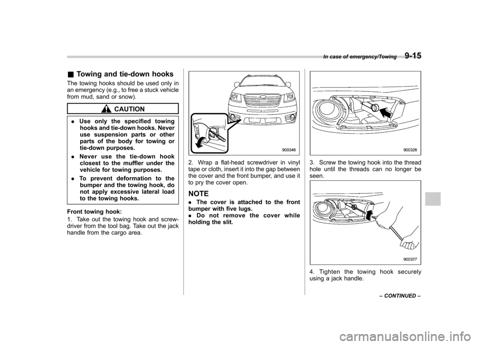
Front towing hook:
1. Take out the towing hook and screw-
driver from the tool bag. Take out the jack
handle from the cargo area.
2. Wrap a flat-head screwdriver in vinyl
tape or cloth, insert it into the gap between
the cover and the front bumper, and use it
to pry the cover open. NOTE . The cover is attached to the front
bumper with five lugs. . Do not remove the cover while
holding the slit.3. Screw the towing hook into the thread
hole until the threads can no longer beseen.
4. Tighten the towing hook securely
using a jack handle.
In case of emergency/Towing9-15
– CONTINUED –
Page 321 of 420

9-16In case of emergency/Towing
After towing, remove the towing hook from
the vehicle and stow it in the tool bag.
Fit the towing hook cover on the bumper.
WARNING
. Do not use the towing hook
except when towing your vehicle.
. Be sure to remove the towing
hook after towing. Leaving the
towing hook mounted on the
vehicle could interfere with prop-
er operation of the SRS airbag
system in a frontal collision.
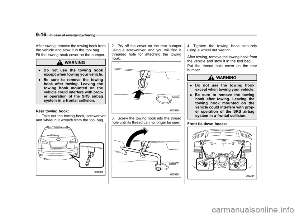
Rear towing hook:
1. Take out the towing hook, screwdriver
and wheel nut wrench from the tool bag.
2. Pry off the cover on the rear bumper
using a screwdriver, and you will find a
threaded hole for attaching the towinghook.
3. Screw the towing hook into the thread
hole until its thread can no longer be seen.
4. Tighten the towing hook securely
using a wheel nut wrench.
After towing, remove the towing hook from
the vehicle and stow it in the tool bag.
Put the thread hole cover on the rear
bumper.
WARNING
. Do not use the towing hook
except when towing your vehicle.
. Be sure to remove the towing
hook after towing. Leaving the
towing hook mounted on the
vehicle could interfere with prop-
er operation of the SRS airbag
system in a frontal collision.
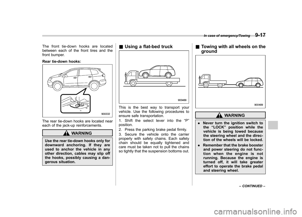
Front tie-down hooks:
Page 322 of 420

The front tie-down hooks are located
between each of the front tires and the
front bumper.
Rear tie-down hooks:
The rear tie-down hooks are located near
each of the jack-up reinforcements.
WARNING
Use the rear tie-down hooks only for
downward anchoring. If they are
used to anchor the vehicle in any
other direction, cables may slip off
the hooks, possibly causing a dan-
gerous situation. &
Using a flat-bed truck
This is the best way to transport your
vehicle. Use the following procedures to
ensure safe transportation.
1. Shift the select lever into the “P ”
position.
2. Press the parking brake pedal firmly.
3. Secure the vehicle onto the carrier
properly with safety chains. Each safety
chain should be equally tightened and
care must be taken not to pull the chains
so tightly that the suspension bottoms out. &
Towing with all wheels on the ground
WARNING
. Never turn the ignition switch to
the “LOCK ”position while the
vehicle is being towed because
the steering wheel and the direc-
tion of the wheels will be locked.
. Remember that the brake booster
and power steering do not func-
tion when the engine is not
running. Because the engine is
turned off, it will take greater
effort to operate the brake pedal
and steering wheel.
In case of emergency/Towing9-17
– CONTINUED –
Page 324 of 420

Maintenance tools
Your vehicle is equipped with the following
maintenance tools.Screwdriver
Towing hook (eye bolt) (if equipped)
Wheel nut wrenchExtension &
Jack and jack handleThe jack and jack handle is stored under
the cargo area.
For how to use the jack, refer to “Flat tires ”
F 9-6.
In case of emergency/Maintenance tools9-19
Page 401 of 420

13-10Consumer information and Reporting safety defects/Tire information
.To maximize the life of each tire
and ensure that the tires wear
uniformly, it is best to rotate the
tires every 7,500 miles (12,000 km).
For information about the tire rota-
tion order, refer to “Tire rotation ”
F 11-26 .
Replace any damaged or
unevenly worn tires at the time of
rotation. After tire rotation, adjust
the tire pressures and make sure
the wheel nuts are correctly tigh-
tened. For information about the
tightening torque and tightening
sequence for the wheel nuts, refer to “Flat tires ”F 9-6 .
& Vehicle load limit –how to
determine
The load capacity of your vehicle is
determined by weight, not by avail-
able cargo space. The load limit of
your vehicle is shown on the
vehicle placard attached to the
driver ’s side B-pillar. Locate the
statement “The combined weight
of occupants and cargo should
never exceed XXX kg or XXX lbs ”on your vehicle
’s placard.
Thevehicleplacardalsoshows
seating capacity of your vehicle.
The total load capacity includes the
total weight of driver and all pas-
sengers and their belongings, any
cargo, any optional equipment such
as a trailer hitch, roof rack or bike
carrier, etc., and the tongue load of
a trailer. Therefore cargo capacity
can be calculated by the followingmethod.
Cargo capacity = Load limit �(total
weight of occupants + total weight
of optional equipment + tongue
load of a trailer (if applicable))
For information about vehicle load-
ing, refer to “Loading your vehicle ”
F 8-12 .
For information about towing capa-
city and weight limits, refer to“ Trailer towing ”F 8-21 . !
Calculating total and load ca-
pacities varying seating con-
figurations
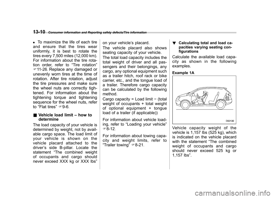
Calculate the available load capa-
city as shown in the followingexamples.
Example 1A
Vehicle capacity weight of the
vehicle is 1,157 lbs (525 kg), which
is indicated on the vehicle placard
with the statement “The combined
weight of occupants and cargo
should never exceed 525 kg or
1,157 lbs ”.
Page 405 of 420

13-14Consumer information and Reporting safety defects/Uniform tire quality grading standards
XXX kg or XXX lbs. 4.The resulting figure equals the
available amount of cargo and
luggage load capacity. For exam-
ple, if the “XXX ”amount equals
1,400 lbs (635 kg) and there will be
five- 150 lbs (68 kg) passengers in
your vehicle, the amount of avail-
able cargo and luggage load capa-
city is 650 lbs. (1,400 �750 (5 6
150) = 650 lbs).
5. Determine the combined weight
of luggage and cargo being loaded
on the vehicle. That weight may not
safely exceed the available cargo
and luggage load capacity calcu-
lated in Step 4. 6. If your vehicle will be towing a
trailer, load from your trailer will be
transferred to your vehicle. Consult
this manual to determine how this
reduces the available cargo and
luggage load capacity of your ve- hicle. Uniform tire quality grading standards
This information indicates the rela-
tive performance of passenger car
tires in the area of treadwear,
traction, and temperature resis-
tance. This is to aid the consumer
in making an informed choice in the
purchase of tires.
Quality grades can be found where
applicable on the tire sidewall be-
tween tread shoulder and maxi-
mum section width. For example:
Treadwear 200 Traction AA Tem-
perature A
The quality grades apply to new
pneumatic tires for use on passen-
ger cars. However, they do not
apply to deep tread, winter type
snow tires, space-saver or tempor-
ary use spare tires, tires with
nominal rim diameters of 12 inches
or less, or to some limited produc-
tion tires.
All passenger car tires must con-form to Federal Safety Require-
ments in addition to these grades. &
Treadwear
The treadwear grade is a compara-
tive rating based on the wear rate of
the tire when tested under con-
trolled conditions on a specified
government test course.
For example, a tire graded 150
would wear one and one-half (1-
1/2) times as well on the govern-
ment course as a tire graded 100.
The relative performance of tires
depends upon the actual conditions
of their use, however, and may
depart significantly from the norm
due to variations in driving habits,
service practices and differences in
road characteristics and climate. & Traction AA, A, B, C
The traction grades, from highest to
lowest, are AA, A, B and C. Those
grades represent the tire ’s ability to
stop on wet pavement as measured
under controlled conditions on spe-
Page 412 of 420

Seatbelt pretensioners............................................ 1-27
Turn signal light .................................................... 11-39
Front seats .................................................................. 1-2
Active head restraint ................................................. 1-6
Forward and backward adjustment ............................. 1-3
Head restraint adjustment ......................................... 1-5
Lumbar support ....................................................... 1-7
Memory function ...................................................... 1-4
Power seat .............................................................. 1-3
Reclining ................................................................. 1-3
Seat height adjustment ............................................. 1-4
Fuel ........................................................................... 7-2
Economy hints ......................................................... 8-2
Filler lid and cap ...................................................... 7-3
Gauge .................................................................... 3-8
Requirements .................................................. 7-2, 12-3
Fuses ...................................................................... 11-34
Main fuse ............................................................. 11-35
Fuses and circuits ...................................................... 12-9
G
GAWR (Gross Axle Weight Rating) .............................. 8-13
Glove box ................................................................... 6-6
GVWR (Gross Vehicle Weight Rating) .......................... 8-13
H
Hazard warning flasher ........................................... 3-5, 9-2
Head restraint adjustment Front seat ............................................................... 1-5
Second-row seat .................................................... 1-12
Third-row seat ....................................................... 1-16 Headlight
Beam leveler. ......................................................... 3-30
Bulb replacement ................................................. 11-36
Bulb wattage ........................................................ 12-12
Control switch ........................................................ 3-27
Flasher .................................................................. 3-28
Indicator light ......................................................... 3-22
HID headlights ......................................................... 11-36
High beam indicator light ............................................. 3-22
High/low beam change (dimmer) .................................. 3-28
HomeLink
®Wireless Control System ............................. 6-17
Hook Coat ..................................................................... 6-12
Convenient tie-down ............................................... 6-16
Shopping bag ........................................................ 6-13
Towing and tie-down ............................................... 9-15
Horn ......................................................................... 3-44
Hose and connections ............................................... 11-10
I
Ignition switch ............................................................. 3-3
Light ...................................................................... 3-4
Illuminated entry ......................................................... 2-10
Illumination brightness control ...................................... 3-29
Immobilizer ................................................................. 2-3
Indicator light (security indicator light) ................. 2-4, 3-21
Indicator light
Cruise control ........................................................ 3-22
Cruise control set ................................................... 3-22
Front fog light ......................................................... 3-22
Headlight ............................................................... 3-22 Index
14-5
Page 417 of 420

14-10Index
Tire ................................................................. 11-21, 12-8 Chains .................................................................. 8-11
Inspection ............................................................ 11-22
Pressures and wear .............................................. 11-23
Replacement ........................................................ 11-26
Rotation ............................................................... 11-26
Size and pressure .................................................. 12-8
Types .................................................................. 11-21
Tire pressure monitoring system (TPMS). .... 7-27, 9-10, 11-21
Warning light ......................................................... 3-14
Tires and wheels. ...................................................... 11-21
Tools ........................................................................ 9-19
Top tether anchorages ........................................ 1-37, 1-40
Towing ...................................................................... 9-14
All wheels on the ground ........................................ 9-17
Flat-bed truck ........................................................ 9-17
Hooks ................................................................... 9-15
Weight.................................................................. 8-21
Traction Control system OFF indicator light .................................................. 3-19
OFF switch ........................................................... 7-25
Trailer
Connecting ............................................................ 8-19
Hitch ............................................................ 8-18, 8-24
Towing .................................................................. 8-21
Towing tips ............................................................ 8-26
Trip meter ................................................................... 3-7
Turn signal Indicator lights ....................................................... 3-21
Lever .................................................................... 3-29 U
Under-floor storage compartment
.................................. 6-16
V
Valet mode ................................................................ 2-18
Vanity mirror ...................................................... 6-5, 11-43
Vehicle Capacity weight ...................................................... 8-12
Identification ........................................................ 12-15
Symbols .................................................................... 3
Vehicle Dynamics Control
Operation indicator light ................................... 3-18, 3-19
System .................................................................. 7-23
Warning light .................................................. 3-18, 3-19
Ventilator .................................................................... 4-2
W
Warning and indicator lights .......................................... 3-9
Warning chimes
Seatbelt. ................................................................ 3-10
Warning light
ABS.............................................................. 3-15, 7-21
All-Wheel Drive ...................................................... 3-18
AT OIL TEMP ......................................................... 3-13
Brake system ......................................................... 3-16
Charge .................................................................. 3-13
CHECK ENGINE .................................................... 3-12
Door open ............................................................. 3-17
Low fuel ................................................................ 3-17
Low tire pressure .................................................... 3-14
Oil pressure ........................................................... 3-13