2013 SUBARU IMPREZA WRX oil
[x] Cancel search: oilPage 7 of 414

4
Mark Name
Hazard warning flasher
Engine hood
Trunk lid (4-door)
Seat heater
Child restraint top tether an- chorages
Child restraint lower an- chorages
Horn
Wiper intermittent
Windshield washer
Windshield wiper mist (for
single wipe)
Rear window wiperMark Name
Rear window washer
Lights
Tail lights, license plate light
and instrument panel illumi- nation
Headlights
Turn signal
Illumination brightness
Fan speed
Instrument panel outlets
Instrument panel outlets and
foot outlets
Foot outlets
Windshield defroster and foot outletsMark Name
Windshield defroster
Rear window defogger/Out-
side mirror defogger/Wind-
shield wiper deicer
Air recirculation
Engine oil
Washer
Door lock (transmitter)
Door unlock (transmitter)
Trunk lid open (4-door) or rear
gate unlock (5-door) (trans- mitter)
Page 25 of 414

22
&Warning and indicator lights
Mark Name Page
Seatbelt warning light 3-13
Front passenger ’s
seatbelt warning light 3-13
SRS airbag system
warning light3-14
/Front passenger
’s
frontal airbag ON indi- cator 3-14
/Front passenger
’s
frontal airbag OFF in- dicator 3-14
CHECK ENGINE
warning light/Malfunc-
tion indicator light3-15
Charge warning light 3-16
Oil pressure warning light
3-16
Rear differential oil
temperature warning
light (STI)3-16
ABS warning light 3-18 Mark Name Page
Brake system warning light
3-19
Door open warning light3-20
Hill start assist warn-
ing light/Hill start assist
OFF indicator light (STI)3-20
Vehicle Dynamics
Control warning light/
Vehicle Dynamics
Control operation indi-
cator light3-20
Vehicle Dynamics
Control OFF indicator
light/Traction Control
OFF indicator light (STI)3-21
Turn signal indicator lights
3-24
High beam indicator light3-24
Front fog light indicator
light (if equipped)
3-24
Security indicator light 3-23
Headlight indicator light
3-24Mark Name Page
Cruise control indica-
tor light
3-24
Cruise control set in-
dicator light3-24
Low fuel warning light 3-20
Low tire pressure
warning light
(U.S.-spec. models)3-16
Shift-up indicator light (STI)
3-23
Driver
’s control center
differential auto indi-
cator light (STI) 3-24
Auto [+] mode indica-
tor light (STI)
3-24
Auto [
�] mode indica-
tor light (STI) 3-25
Driver
’s control center
differential indicator
and warning lights (STI) 3-25
REV indicator light (STI)
3-25
Sport (S) mode indi-
cator light (STI)3-23
Page 46 of 414

CAUTION
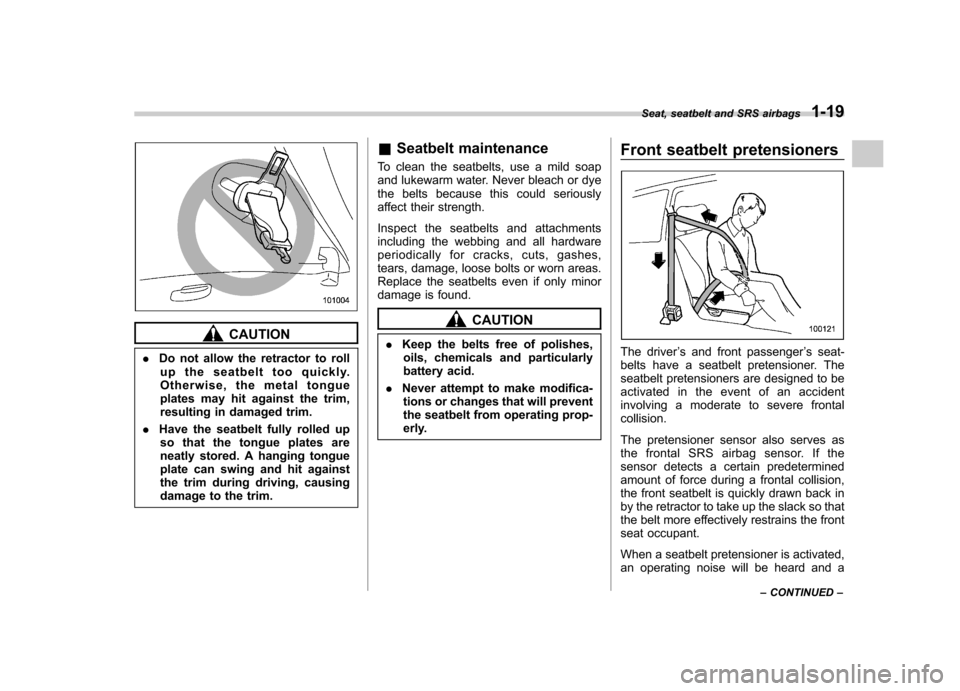
. Do not allow the retractor to roll
up the seatbelt too quickly.
Otherwise, the metal tongue
plates may hit against the trim,
resulting in damaged trim.
. Have the seatbelt fully rolled up
so that the tongue plates are
neatly stored. A hanging tongue
plate can swing and hit against
the trim during driving, causing
damage to the trim. &
Seatbelt maintenance
To clean the seatbelts, use a mild soap
and lukewarm water. Never bleach or dye
the belts because this could seriously
affect their strength.
Inspect the seatbelts and attachments
including the webbing and all hardware
periodically for cracks, cuts, gashes,
tears, damage, loose bolts or worn areas.
Replace the seatbelts even if only minor
damage is found.
CAUTION
. Keep the belts free of polishes,
oils, chemicals and particularly
battery acid.
. Never attempt to make modifica-
tions or changes that will prevent
the seatbelt from operating prop-
erly. Front seatbelt pretensioners
The driver
’s and front passenger ’s seat-
belts have a seatbelt pretensioner. The
seatbelt pretensioners are designed to be
activated in the event of an accident
involving a moderate to severe frontalcollision.
The pretensioner sensor also serves as
the frontal SRS airbag sensor. If the
sensor detects a certain predetermined
amount of force during a frontal collision,
the front seatbelt is quickly drawn back in
by the retractor to take up the slack so that
the belt more effectively restrains the front
seat occupant.
When a seatbelt pretensioner is activated,
an operating noise will be heard and a Seat, seatbelt and SRS airbags
1-19
– CONTINUED –
Page 96 of 414

&Replacing the battery
CAUTION
. Do not let dust, oil or water get on
or in the transmitter when repla-
cing the battery.
. Be careful not to damage the
printed circuit board in the trans-
mitter when replacing the battery.
. Be careful not to allow children to
touch the battery and any re-
moved parts; children could
swallow them.
. There is a danger of explosion if
an incorrect replacement battery
is used. Replace only with the
same or equivalent type of bat-
tery.
. Batteries should not be exposed
to excessive heat such as sun-
shine, fire or the like.
When the transmitter battery begins to get
weak, transmitter range will begin to
decrease. Replace the battery as soon
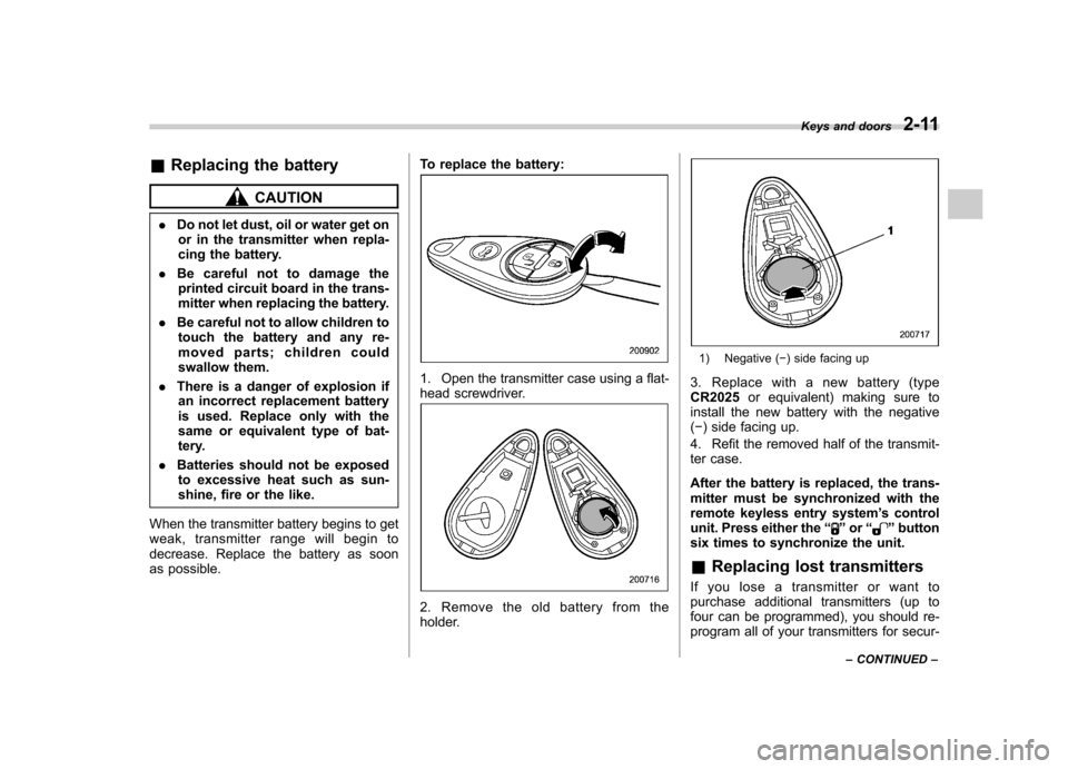
as possible. To replace the battery:
1. Open the transmitter case using a flat-
head screwdriver.
2. Remove the old battery from the
holder.
1) Negative (
�) side facing up
3. Replace with a new battery (type CR2025 or equivalent) making sure to
install the new battery with the negative( � ) side facing up.
4. Refit the removed half of the transmit-
ter case.
After the battery is replaced, the trans-
mitter must be synchronized with the
remote keyless entry system ’s control
unit. Press either the “
”or “”button
six times to synchronize the unit. & Replacing lost transmitters
If you lose a transmitter or want to
purchase additional transmitters (up to
four can be programmed), you should re-
program all of your transmitters for secur- Keys and doors
2-11
– CONTINUED –
Page 116 of 414

Ignition switch..................................................... 3-3
LOCK .................................................................. 3-3
Acc..................................................................... 3-4
ON...................................................................... 3-4
START ................................................................ 3-4
Key reminder chime ............................................ 3-4
Ignition switch light ............................................. 3-4
Hazard warning flasher ....................................... 3-5
Meters and gauges. ............................................. 3-5
Combination meter illumination ........................... 3-5
Canceling the function for meter/gauge needle movement upon turning on the ignition switch ............................................................... 3-6
Meter/Gauge needle illumination setting (except STI) ................................................................... 3-6
Speedometer ....................................................... 3-7
Odometer/Trip meter ............................................ 3-7
Tachometer ......................................................... 3-9
Fuel gauge .......................................................... 3-9
Temperature gauge ............................................ 3-10
REV indicator light and buzzer (STI). ................ 3-10
Setting the alarm-level engine speed ................... 3-11
Deactivating the REV alarm system ..................... 3-12
Warning and indicator lights ............................. 3-12
Seatbelt warning light and chime ........................ 3-13
SRS airbag system warning light ........................ 3-14
Front passenger ’s frontal airbag ON and OFF
indicators ......................................................... 3-14
CHECK ENGINE warning light/Malfunction indicator light ................................................... 3-15 Charge warning light
.......................................... 3-16
Oil pressure warning light .................................. 3-16
Rear differential oil temperature warning light (STI) ................................................................ 3-16
Low tire pressure warning light (U.S.-spec. models) ........................................................... 3-16
ABS warning light .............................................. 3-18
Brake system warning light ................................ 3-19
Low fuel warning light ....................................... 3-20
Hill start assist warning light/Hill start assist OFF indicator light (STI) .......................................... 3-20
Door open warning light .................................... 3-20
Vehicle Dynamics Control warning light/Vehicle Dynamics Control operation indicator light .. ..... 3-20
Vehicle Dynamics Control OFF indicator light/ Traction Control OFF indicator light (STI)..... ..... 3-21
Security indicator light ....................................... 3-23
SI-DRIVE indicator light (STI) .............................. 3-23
Shift-up indicator light (STI) ............................... 3-23
Turn signal indicator lights ................................. 3-24
High beam indicator light ................................... 3-24
Cruise control indicator light .............................. 3-24
Cruise control set indicator light ........................ 3-24
Front fog light indicator light (if equipped) ..... ..... 3-24
Headlight indicator light ..................................... 3-24
Driver ’s control center differential auto indicator
light (STI) ........................................................ 3-24
Driver ’s control center differential indicator and
warning lights (STI) .......................................... 3-25
REV indicator light (STI) ..................................... 3-25
Clock .................................................................. 3-26Instruments and controls
3
Page 127 of 414

3-12Instruments and controls
to OFF, OFF to ON, or the vehicle starts
moving before the setting procedure isfinished..Setting the speed is impossible
when the vehicle is moving.. The set engine speed may differ
from the engine speed shown by the
tachometer. Use the engine speed
shown by the tachometer as a roughguide.. If the setting operation is performed
with the engine switch turned off, the
REV indicator light turns off and the
setting operation is aborted when you
have stopped the setting operation for
approximately 10 seconds. . If the setting operation is performed
with the engine switch turned off, the
REV indicator light turns off and the
setting operation is aborted when you
open and close the driver ’s door.
& Deactivating the REV alarm system
To deactivate the REV indicator light and
buzzer functions of the REV alarm system,
set the thousands place of the alarm-level
engine speed to “–”. Warning and indicator lights
Several of the warning and indicator lights
illuminate momentarily and then turn off
when the ignition switch is initially turned
to the
“ON ”position. This permits check-
ing the operation of the bulbs.
Apply the parking brake and turn the
ignition switch to the “ON ”position. For
the system check, the following lights
illuminate and turn off after several sec-
onds or after the engine has started:
: Seatbelt warning light (The seatbelt warning light turns off
only when the driver fastens theseatbelt.)
: Front passenger ’s seatbelt warning
light
(The seatbelt warning light turns off
only when the front seat passenger
fastens the seatbelt.)
: SRS airbag system warning light
ON /
: Front passenger ’s frontal airbag
ON indicator light
/: Front passenger ’s frontal airbag
OFF indicator light
: CHECK ENGINE warning light/Mal- function indicator light
: Charge warning light
: Oil pressure warning light
: Rear differential oil temperature warn-ing light (STI)
: Low tire pressure warning light (U.S.- spec. models)
/: ABS warning light
/: Brake system warning light
: Low fuel warning light
: Hill start assist warning light/Hill start assist OFF indicator light (STI)
: Door open warning light
: Vehicle Dynamics Control warning light/Vehicle Dynamics Control opera-
tion indicator light
: Vehicle Dynamics Control OFF indica-tor light/Traction Control OFF indicator
light (STI)
: Cruise control indicator light
: Cruise control set indicator light
: Shift-up indicator light (STI)
: REV indicator light (STI)
:Driver ’s control center differential
indicator and warning lights (STI)
Page 131 of 414

3-16Instruments and controls
The CHECK ENGINE warning light may
stop blinking and illuminate steadily after
several driving trips. You should have your
vehicle checked by an authorized
SUBARU dealer immediately. &Charge warning light
If this light illuminates when the engine is
running, it may indicate that the charging
system is not working properly.
If the light illuminates while driving or does
not turn off after the engine starts, stop the
engine at the first safe opportunity and
check the alternator belt. If the belt is
loose, broken or if the belt is in good
condition but the light remains illuminated,
contact your nearest SUBARU dealer
immediately. &Oil pressure warning light
If this light illuminates when the engine is
running, it may indicate that the engine oil
pressure is low and the lubricating system
is not working properly.
If the light illuminates while driving or does
not turn off after the engine starts, stop the
engine at the first safe opportunity and
check the engine oil level. If the oil level is
low, add oil immediately. If the engine oil is
at the proper level but the light remains illuminated, contact your nearest
SUBARU dealer immediately.
For details about checking the engine oil
level or adding the engine oil, refer to“
Engine oil ”F 11-8.
CAUTION
Do not operate the engine with the
oil pressure warning light illumi-
nated. This may cause serious en-
gine damage.
& Rear differential oil
temperature warning
light (STI)
CAUTION
If the R.DIFF TEMP warning light
illuminates, reduce vehicle speed
and stop the vehicle in a safe
location as soon as possible. Con-
tinuing to drive with this light illumi-
nated may damage the rear differ-
ential and other parts of the power-train.
If this light illuminates when the engine is
running, it may indicate that the rear
differential oil temperature is too hot.
At this time, the driver ’s control center differential will automatically cancel the
current torque-distribution ratio setting and
adopt its minimum ratio.
If the light illuminates while driving, reduce
vehicle speed and stop the vehicle in the
nearest safe location. Park the vehicle for
several minutes. After the light turns off,
you can start driving.
If the light does not turn off, contact the
nearest SUBARU dealer for service.
NOTE . If the tire pressures are not correct
and/or the tires are not all the same
size and brand, the rear differential will
be heavily loaded when the vehicle is
driven, resulting in an abnormally high
oil temperature.. The rear differential oil will deterio-
rate if its temperature increases en-
ough for the rear differential oil tem-
perature warning light to illuminate. It is
advisable to have the rear differential
oil replaced as soon as possible. & Low tire pressure
warning light (U.S.-spec. models)
When the ignition switch is turned to the “ON ”position, the low tire pressure warn-
ing light will illuminate for approximately 2
Page 166 of 414

Ventilator.............................................................. 4-2
Airflow selection ................................................. 4-2
Center and side ventilators .................................. 4-3
Manual climate control system (if equipped) ..................................................... 4-3
Control panel ...................................................... 4-3
Heater operation ................................................. 4-5
Air conditioner operation ..................................... 4-7
Automatic climate control system (if equipped) ..................................................... 4-8
Control panel ...................................................... 4-8
To use as full-automatic climate control system .............................................................. 4-8
To use as semi-automatic climate control system .............................................................. 4-8
Fan speed control dial ......................................... 4-9
Temperature control dial ...................................... 4-9
Airflow control dial .............................................. 4-9
Air inlet selection button .................................... 4-10 Air conditioner button
........................................ 4-11
Temperature sensors ......................................... 4-11
Operating tips for heater and air conditioner ...................................................... 4-12
Cleaning ventilation grille ................................... 4-12
Efficient cooling after parking in direct sunlight ........................................................... 4-12
Lubrication oil circulation in the refrigerant circuit .............................................................. 4-12
Checking air conditioning system before summer season ............................................................ 4-12
Cooling and dehumidifying in high humidity and low temperature weather conditions ................. 4-12
Air conditioner compressor shut-off when engine is heavily loaded .............................................. 4-13
Refrigerant for your climate control system ... ..... 4-13
Air filtration system ........................................... 4-13
Replacing an air filter ......................................... 4-13Climate control
4