2013 SUBARU IMPREZA WRX tow
[x] Cancel search: towPage 324 of 414

&When checking or servicing
in the engine compartment
while the engine is running
WARNING
A running engine can be dangerous.
Keep your fingers, hands, clothing,
hair and tools away from the cooling
fan, belts and any other moving
engine parts. Removing rings,
watches and ties is advisable. Engine hood
WARNING
Always check that the hood is
properly locked before you start
driving. If it is not, it might fly open
while the vehicle is moving and
block your view, which may cause
an accident and serious bodily in-
jury.
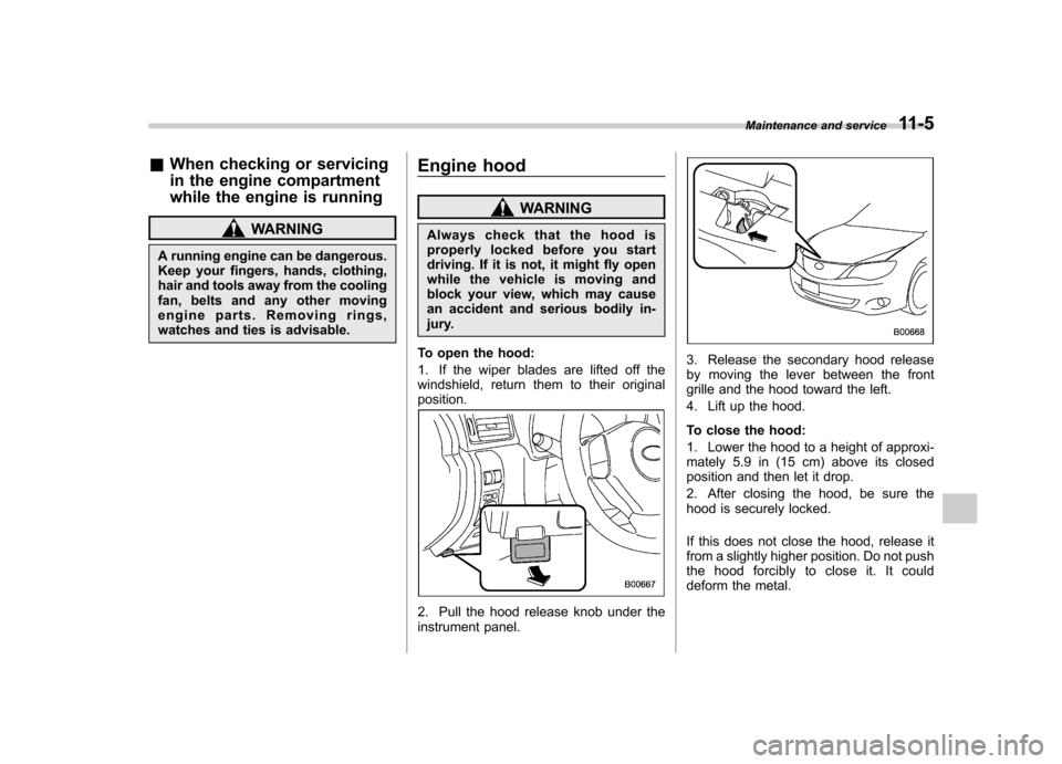
To open the hood:
1. If the wiper blades are lifted off the
windshield, return them to their originalposition.
2. Pull the hood release knob under the
instrument panel.
3. Release the secondary hood release
by moving the lever between the front
grille and the hood toward the left.
4. Lift up the hood.
To close the hood:
1. Lower the hood to a height of approxi-
mately 5.9 in (15 cm) above its closed
position and then let it drop.
2. After closing the hood, be sure the
hood is securely locked.
If this does not close the hood, release it
from a slightly higher position. Do not push
thehoodforciblytocloseit.Itcould
deform the metal. Maintenance and service
11-5
Page 354 of 414

3. Pull the wiper blade assembly toward
you to remove it from the wiper arm.
4. Install the wiper blade assembly to the
wiper arm. Make sure that it locks in place.
5. Hold the wiper arm by hand and slowly
lower it in position.&
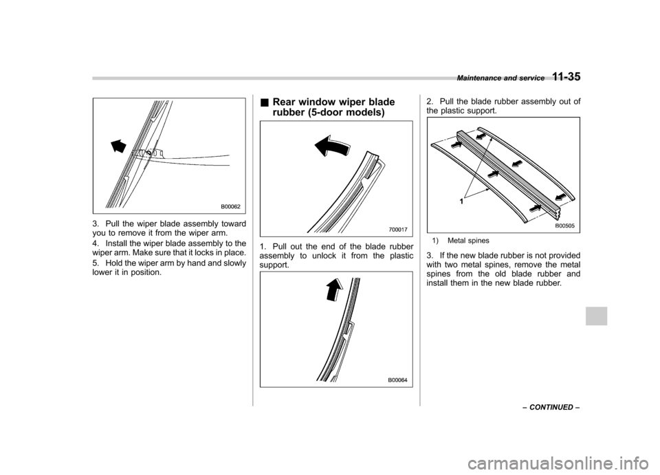
Rear window wiper blade
rubber (5-door models)
1. Pull out the end of the blade rubber
assembly to unlock it from the plasticsupport.
2. Pull the blade rubber assembly out of
the plastic support.
1) Metal spines
3. If the new blade rubber is not provided
with two metal spines, remove the metal
spines from the old blade rubber and
install them in the new blade rubber. Maintenance and service
11-35
– CONTINUED –
Page 395 of 414

13-10Consumer information and Reporting safety defects
& Tire care –maintenance and
safety practices
. Check on a daily basis that the
tires are free from serious damage,
nails, and stones. At the same time,
check the tires for abnormal wear. . Inspect the tire tread regularly
and replace the tires before their
tread wear indicators become visi-
ble. When a tire ’streadwear
indicator becomes visible, the tire
is worn beyond the acceptable limit
and must be replaced immediately.
With a tire in this condition, driving
at even low speeds in wet weather
can cause the vehicle to hydro-
plane. Possible resulting loss of
vehiclecontrolcanleadtoanaccident. . To maximize the life of each tire
and ensure that the tires wear
uniformly, it is best to rotate the
tires every 7,500 miles (12,000 km).
For information about the tire rota-
tion order, refer to “Tire rotation ”
F 11-29 .
Replace any damaged or
unevenly worn tires at the time of rotation. After tire rotation, adjust
the tire pressures and make sure
the wheel nuts are correctly tigh-
tened. For information about the
tightening torque and tightening
sequence for the wheel nuts, refer to
“Flat tires ”F 9-5 .
& Vehicle load limit –how to
determine
The load capacity of your vehicle is
determined by weight, not by avail-
able cargo space. The load limit of
your vehicle is shown on the
vehicle placard attached to the
driver ’s side B-pillar. Locate the
statement “The combined weight
of occupants and cargo should
never exceed XXX kg or XXX lbs ”
on your vehicle ’s placard.
Thevehicleplacardalsoshows
seating capacity of your vehicle.
The total load capacity includes the
total weight of driver and all pas-
sengers and their belongings, any
cargo, any optional equipment such
as a trailer hitch, roof rack or bike carrier, etc., and the tongue load of
a trailer. Therefore cargo capacity
can be calculated by the following method.
Cargo capacity = Load limit
�(total
weight of occupants + total weight
of optional equipment + tongue
load of a trailer (if applicable))
For information about vehicle load-
ing, refer to “Loading your vehicle ”
F 8-10 .
NOTE
Your vehicle is neither designed
nor intended to be used for
trailer towing. Therefore, never
tow a trailer with your vehicle.
Page 397 of 414

13-12Consumer information and Reporting safety defects
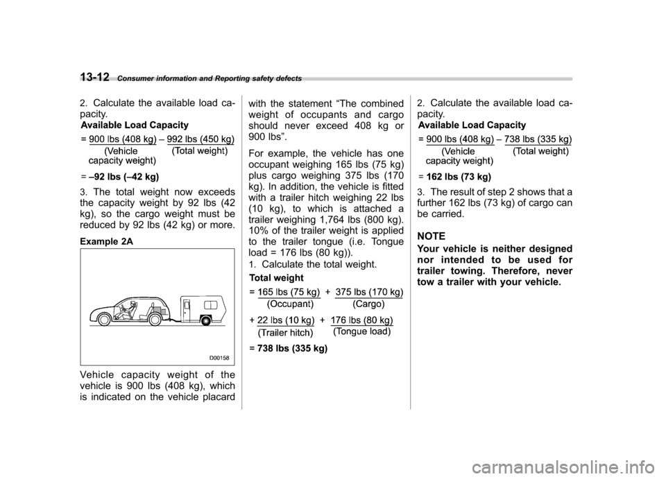
2. Calculate the available load ca-
pacity.
3. The total weight now exceeds
the capacity weight by 92 lbs (42
kg), so the cargo weight must be
reduced by 92 lbs (42 kg) or more.
Example 2A
Vehicle capacity weight of the
vehicle is 900 lbs (408 kg), which
is indicated on the vehicle placard with the statement
“The combined
weight of occupants and cargo
should never exceed 408 kg or
900 lbs ”.
For example, the vehicle has one
occupant weighing 165 lbs (75 kg)
plus cargo weighing 375 lbs (170
kg). In addition, the vehicle is fitted
with a trailer hitch weighing 22 lbs
(10 kg), to which is attached a
trailer weighing 1,764 lbs (800 kg).
10% of the trailer weight is applied
to the trailer tongue (i.e. Tongue
load = 176 lbs (80 kg)).
1. Calculate the total weight.
2. Calculate the available load ca-
pacity.
3. The result of step 2 shows that a
further 162 lbs (73 kg) of cargo can
be carried. NOTE
Your vehicle is neither designed
nor intended to be used for
trailer towing. Therefore, never
tow a trailer with your vehicle.
Page 398 of 414

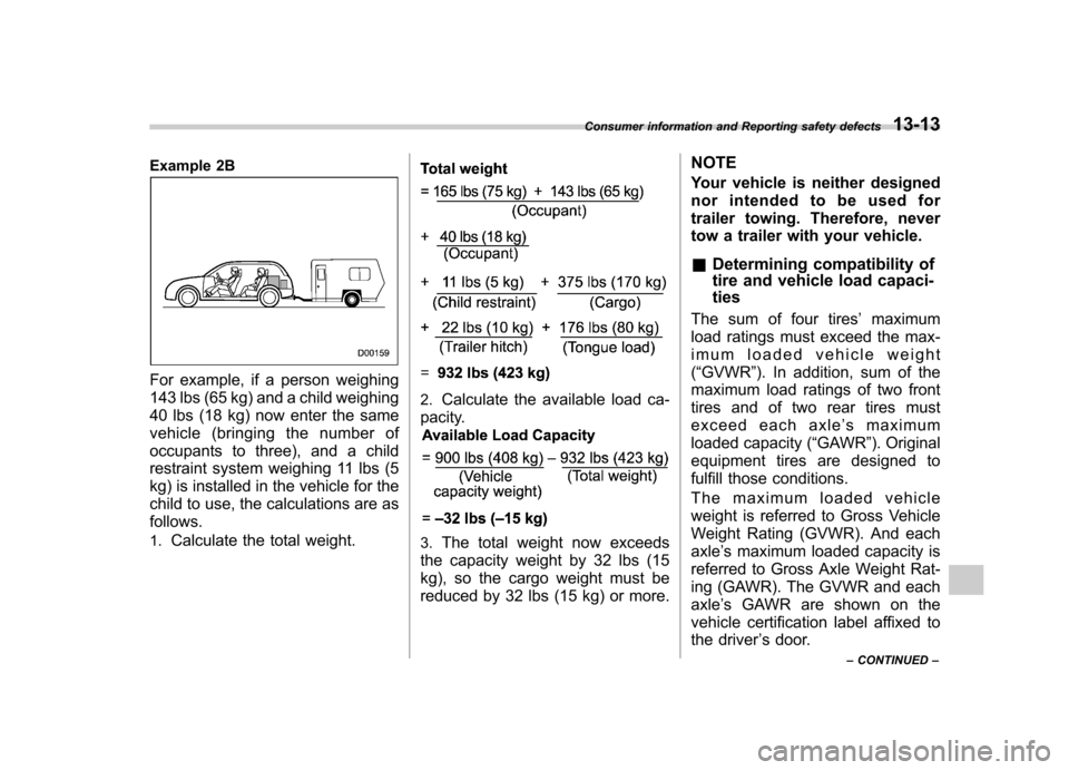
Example 2B
For example, if a person weighing
143 lbs (65 kg) and a child weighing
40 lbs (18 kg) now enter the same
vehicle (bringing the number of
occupants to three), and a child
restraint system weighing 11 lbs (5
kg) is installed in the vehicle for the
child to use, the calculations are as follows. 1.Calculate the total weight.
2.Calculate the available load ca-
pacity.
3. The total weight now exceeds
the capacity weight by 32 lbs (15
kg), so the cargo weight must be
reduced by 32 lbs (15 kg) or more. NOTE
Your vehicle is neither designed
nor intended to be used for
trailer towing. Therefore, never
tow a trailer with your vehicle. &
Determining compatibility of
tire and vehicle load capaci- ties
The sum of four tires ’maximum
load ratings must exceed the max-
imum loaded vehicle weight( “GVWR ”). In addition, sum of the
maximum load ratings of two front
tires and of two rear tires must
exceed each axle ’smaximum
loaded capacity ( “GAWR ”). Original
equipment tires are designed to
fulfill those conditions.
The maximum loaded vehicle
weight is referred to Gross Vehicle
Weight Rating (GVWR). And eachaxle ’s maximum loaded capacity is
referred to Gross Axle Weight Rat-
ing (GAWR). The GVWR and each axle ’s GAWR are shown on the
vehicle certification label affixed to
the driver ’s door.
Consumer information and Reporting safety defects
13-13
– CONTINUED –
Page 399 of 414

13-14Consumer information and Reporting safety defects
The GVWR and front and rear
GAWRs are determined by not only
the maximum load rating of tires but
also loaded capacities of the vehi-cle ’s suspension, axles and other
parts of the body.
Therefore, this means that the
vehicle cannot necessarily be
loaded up to the tire ’s maximum
load rating on the tire sidewall. & Adverse safety conse-
quences of overloading on
handling and stopping and
on tires
Overloading could affect vehicle
handling, stopping distance, and
vehicle and tire performance in the
following ways. This could lead to
an accident and possibly result in
severe personal injury. . Vehicle stability will deteriorate.
. Heavy and/or high-mounted
loads could increase the risk of
rollover. . Stopping distance will increase.
. Brakes could overheat and fail. .
Suspension, bearings, axles and
other body parts could break or
experience accelerated wear that
will shorten vehicle life.
. Tires could fail.
. Tread separation could occur.
. Tire could separate from its rim.
& Steps for Determining Cor-
rect Load Limit
1. Locate the statement “The com-
bined weight of occupants and
cargo should never exceed XXX
kg or XXX lbs. ”on your vehicle ’s
placard.
2. Determine the combined weight
of the driver and passengers that
will be riding in your vehicle. 3. Subtract the combined weight of
the driver and passengers from
XXX kg or XXX lbs. 4. The resulting figure equals the
available amount of cargo and
luggage load capacity. For exam-
ple, if the “XXX ”amount equals
1,400 lbs (635 kg) and there will be
five- 150 lbs (68 kg) passengers in your vehicle, the amount of avail-
able cargo and luggage load capa-
city is 650 lbs. (1,400
�750 (5 6
150) = 650 lbs)
5. Determine the combined weight
of luggage and cargo being loaded
on the vehicle. That weight may not
safely exceed the available cargo
and luggage load capacity calcu-
lated in Step 4. 6. If your vehicle will be towing a
trailer, load from your trailer will be
transferred to your vehicle. Consult
this manual to determine how this
reduces the available cargo and
luggage load capacity of your ve-hicle. NOTE
Your vehicle is neither designed
nor intended to be used for
trailer towing. Therefore, never
tow a trailer with your vehicle.
Page 407 of 414

14-6Index
Shopping bag ........................................................ 6-11
Towing and tie-down ............................................... 9-13
Horn ......................................................................... 3-49
Hose and connections ............................................... 11-11
I
Ignition switch .............................................................. 3-3
Light ....................................................................... 3-4
Illumination brightness control ...................................... 3-31
Immobilizer. ................................................................. 2-2
Indicator light (security indicator light) ....................... 3-23
Indicator light Cruise control ........................................................ 3-24
Cruise control set ................................................... 3-24
Front fog light ........................................................ 3-24
Headlight .............................................................. 3-24
High beam ............................................................ 3-24
Hill start assist OFF ................................................ 3-20
Immobilizer. ........................................................... 3-23
REV ..................................................................... 3-25Security ................................................................ 3-23
Shift-up ................................................................. 3-23
SI-DRIVE .............................................................. 3-23
Traction control OFF ............................................... 3-21
Turn signal ............................................................ 3-24
Vehicle Dynamics Control OFF ................................ 3-21
Vehicle Dynamics Control operation ................. 3-20, 3-21
Information display ..................................................... 3-26
Inside mirror .............................................................. 3-38
Interior lights ............................................................... 6-2
Internal trunk lid release handle ................................... 2-24 iPod
®operations
........................................................ 5-26
J
Jack and jack handle ................................................... 9-4
Jack-up point .............................................................. 9-5
Jump starting .............................................................. 9-9
K
Key............................................................................ 2-2 Number .................................................................. 2-2
Reminder chime ...................................................... 3-4
Replacement. .......................................................... 2-3
L
Leather seat materials ................................................. 10-5
License plate light ..................................................... 11-45
Light Backup (4-door) ................................................... 11-43
Backup (5-door) ................................................... 11-45
Cargo area .................................................... 6-2, 11-47
Control switch ........................................................ 3-29
Daytime running ..................................................... 3-30
Dome ............................................................ 6-2, 11-47
Front fog ..................................................... 3-34, 11-42
Front position ......................................................... 3-29
Front side marker ................................................. 12-14
High-mounted stop ............................................... 11-47
Ignition switch ......................................................... 3-4
License plate ....................................................... 11-45
Map .............................................................. 6-3, 11-46
Rear combination ................................................. 11-43
Page 411 of 414

14-10Index
Tie-down hooks ......................................................... 9-13
Tire ................................................................. 11-23, 12-9 Chains .................................................................... 8-9
Inspection ............................................................ 11-25
Pressures and wear .............................................. 11-25
Replacement ........................................................ 11-29
Rotation ............................................................... 11-29
Size and pressure .................................................. 12-9
Types .................................................................. 11-23
Tire pressure monitoring system (TPMS). ...... 7-32, 9-8, 11-24
Warning light ......................................................... 3-16
Tires and wheels. ...................................................... 11-23
Tools .......................................................................... 9-3
Top tether anchorages ........................................ 1-29, 1-31
Towing ...................................................................... 9-12
All wheels on the ground ........................................ 9-15
Flat-bed truck ........................................................ 9-15
Hooks ................................................................... 9-13
Trailer Towing .................................................................. 8-13
Trip meter ................................................................... 3-7
Trunk lid ................................................................... 2-23
Release handle ..................................................... 2-24
Trunk light ................................................................ 11-47
Turn signal Indicator lights ....................................................... 3-24
Lever .................................................................... 3-31
U
Under-floor storage compartment ................................. 6-14
USB storage device operations .................................... 5-26 V
Valet mode
................................................................ 2-17
Vanity mirror ............................................................... 6-4
Vehicle Capacity weight ...................................................... 8-10
Identification ........................................................ 12-17
Symbols .................................................................... 3
Vehicle Dynamics Control Mode switch .......................................................... 7-29
OFF indicator light .................................................. 3-21
OFF switch ............................................................ 7-30
Operation indicator light ................................... 3-20, 3-21
System .................................................................. 7-28
Warning light .......................................................... 3-20
Ventilator .................................................................... 4-2
W
Warning and indicator lights ......................................... 3-12
Warning light ABS...................................................................... 3-18
Brake system ......................................................... 3-19
Charge .................................................................. 3-16
CHECK ENGINE .................................................... 3-15
Door open ............................................................. 3-20
Driver ’s Control Center Differential ............................ 3-25
Hill start assist ....................................................... 3-20
Low fuel ................................................................ 3-20
Low tire pressure .................................................... 3-16
Oil pressure ........................................................... 3-16
Rear differential oil temperature ................................ 3-16
Seatbelt. ................................................................ 3-13