2013 SUBARU FORESTER belt
[x] Cancel search: beltPage 81 of 436
1-56Seat, seatbelt and SRS airbags
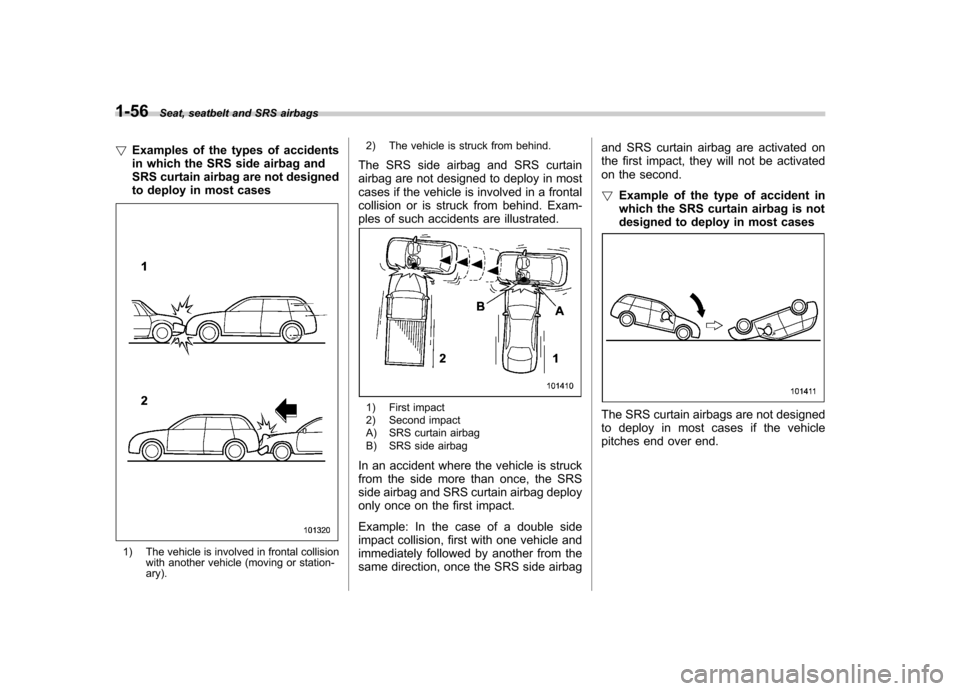
! Examples of the types of accidents
in which the SRS side airbag and
SRS curtain airbag are not designed
to deploy in most cases
1) The vehicle is involved in frontal collision
with another vehicle (moving or station- ary). 2) The vehicle is struck from behind.
The SRS side airbag and SRS curtain
airbag are not designed to deploy in most
cases if the vehicle is involved in a frontal
collision or is struck from behind. Exam-
ples of such accidents are illustrated.
1) First impact
2) Second impact
A) SRS curtain airbag
B) SRS side airbag
In an accident where the vehicle is struck
from the side more than once, the SRS
side airbag and SRS curtain airbag deploy
only once on the first impact.
Example: In the case of a double side
impact collision, first with one vehicle and
immediately followed by another from the
same direction, once the SRS side airbag and SRS curtain airbag are activated on
the first impact, they will not be activated
on the second. !
Example of the type of accident in
which the SRS curtain airbag is not
designed to deploy in most casesThe SRS curtain airbags are not designed
to deploy in most cases if the vehicle
pitches end over end.
Page 82 of 436
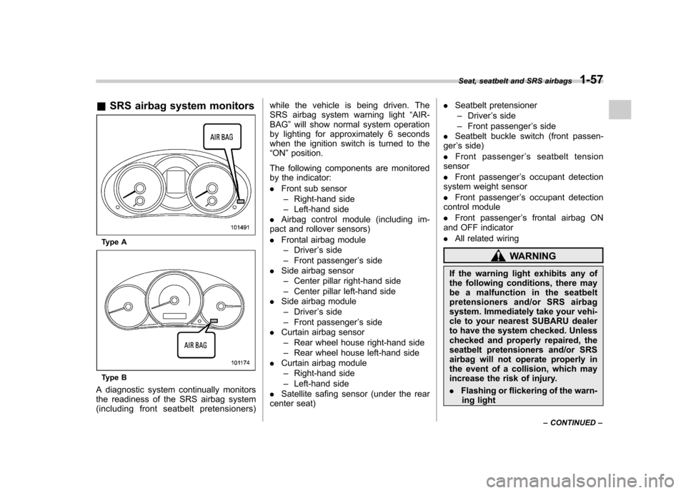
&SRS airbag system monitors
Type A
Type B
A diagnostic system continually monitors
the readiness of the SRS airbag system
(including front seatbelt pretensioners) while the vehicle is being driven. The
SRS airbag system warning light
“AIR-
BAG ”will show normal system operation
by lighting for approximately 6 seconds
when the ignition switch is turned to the“ ON ”position.
The following components are monitored
by the indicator: . Front sub sensor
– Right-hand side
– Left-hand side
. Airbag control module (including im-
pact and rollover sensors). Frontal airbag module
– Driver ’s side
– Front passenger ’s side
. Side airbag sensor
– Center pillar right-hand side
– Center pillar left-hand side
. Side airbag module
– Driver ’s side
– Front passenger ’s side
. Curtain airbag sensor
– Rear wheel house right-hand side
– Rear wheel house left-hand side
. Curtain airbag module
– Right-hand side
– Left-hand side
. Satellite safing sensor (under the rear
center seat) .
Seatbelt pretensioner
– Driver ’s side
– Front passenger ’s side
. Seatbelt buckle switch (front passen-
ger ’s side)
. Front passenger ’s seatbelt tension
sensor. Front passenger ’s occupant detection
system weight sensor. Front passenger ’s occupant detection
control module. Front passenger ’s frontal airbag ON
and OFF indicator. All related wiring
WARNING
If the warning light exhibits any of
the following conditions, there may
be a malfunction in the seatbelt
pretensioners and/or SRS airbag
system. Immediately take your vehi-
cle to your nearest SUBARU dealer
to have the system checked. Unless
checked and properly repaired, the
seatbelt pretensioners and/or SRS
airbag will not operate properly in
the event of a collision, which may
increase the risk of injury. . Flashing or flickering of the warn-
ing light
Seat, seatbelt and SRS airbags
1-57
– CONTINUED –
Page 83 of 436
1-58Seat, seatbelt and SRS airbags
.No illumination of the warning
light when the ignition switch is
first turned to the “ON ”position
. Continuous illumination of the
warning light
. Illumination of the warning light
while driving
& SRS airbag system servicing
WARNING
. When discarding an airbag mod-
ule or scrapping the entire vehi-
cle damaged by a collision, con-
sult your SUBARU dealer.
. The SRS airbag has no user-
serviceable parts. Do not use
electrical test equipment on any
circuit related to the SRS airbag
system. For required servicing of
the SRS airbag, consult your
nearest SUBARU dealer. Tamper-
ing with or disconnecting thesystem ’s wiring could result in
accidental inflation of the SRS
airbag or could make the system
inoperative, which may result in
serious injury.
CAUTION
If you need service or repair in areas
indicated in the following list, have
the work performed by an author-
ized SUBARU dealer. The SRS air-
bag control module, impact sensors
and airbag modules are stored in
these areas. . Under the center console
. On both the right and left sides at
the front of the vehicle
. Steering wheel and column and
nearby areas
. Top of the dashboard on front
passenger ’s side and nearby
areas
. Each front seat and nearby area
. Inside each center pillar
. In each roof side (from the front
pillar to a point over the rear seat)
. Between the rear seat cushion
and rear wheel house on each side
. Under the rear center seat
In the event that the SRS airbag is
deployed, replacement of the system
should be performed only by an author-
ized SUBARU dealer. When the compo- nents of the SRS airbag system are
replaced, use only genuine SUBARUparts.
NOTE
In the following cases, contact your
SUBARU dealer as soon as possible. . The front part of the vehicle was
damaged in an accident in which either
or both of the frontal airbags did not
deploy.. The pad of the steering wheel, the
cover over the front passenger ’s SRS
frontal airbag, or either roof side (from
the front pillar to a point over the rear
seat) is scratched, cracked, or other-
wise damaged.. Center pillar, rear wheel house or
rear sub frame, or an area near these
parts, was involved in an accident in
which the SRS side airbag and SRS
curtain airbag did not deploy.. The fabric or leather of either front
seatback is cut, frayed, or otherwisedamaged.. The rear part of the vehicle was
involved in an accident in which no
SRS airbag deployed.
Page 84 of 436
&Precautions against vehicle modification
WARNING
To avoid accidental activation of the
system or rendering the system
inoperative, which may result in
serious injury, no modifications
should be made to any components
or wiring of the SRS airbag system.
This includes the following modifi- cations. . Installation of custom steering
wheels
. Attachment of additional trim
materials to the dashboard
. Installation of custom seats
. Replacement of seat fabric or
leather
. Installation of additional fabric or
leather on the front seat
. Attachment of a hands-free mi-
crophone or any other accessory
to a front pillar, a center pillar, a
rear pillar, the windshield, a side
window, an assist grip, or any
other cabin surface that would be
near a deploying SRS curtainairbag. .
Installation of additional electri-
cal/electronic equipment such as
a mobile two-way radio on or
near the SRS airbag system
components and/or wiring is not
advisable. This could interfere
with proper operation of the
SRS airbag system.
CAUTION
Do not perform any of the following
modifications. Such modifications
can interfere with proper operation
of the SRS airbag system. . Attachment of any equipment
(bush bar, winches, snow plow,
skid plate, etc.) other than genu-
ine SUBARU accessory parts to
the front end.
. Modification of the suspension
system or front end structure.
. Installation of a tire of different
size and construction from the
tires specified on the vehicle
placard attached to the driver ’s
door pillar or specified for indivi-
dual vehicle models in this Own-er ’s Manual.
. Attachment of any equipment
(side steps or side sill protectors, etc.) other than genuine SUBARU
accessory parts to the side body.
Always consult your SUBARU dealer if
you want to install any accessory parts on
your vehicle. Seat, seatbelt and SRS airbags
1-59
Page 90 of 436

1) Rotate the lock lever rearward.
2) Close the door.
To lock the door from the outside without
the key, rotate the lock lever rearward and
then close the door.
To lock the door from the outside using the
power door locking switch, push the front
side of the switch ( “LOCK ”side) and then
close the door. In this case, all closed
doors and the rear gate are locked at the
same time.
Always make sure that all doors and the
rear gate are locked before leaving yourvehicle. NOTE
Make sure that you do not leave the key
inside the vehicle when locking the doors from the outside without the key.
& Locking and unlocking from
the inside
1) Lock
2) Unlock
To lock the door from the inside, rotate the
lock lever rearward. To unlock the door
from the inside, rotate the lock leverforward.
The red mark on the lock lever appears
when the door is unlocked.
Pull the inside door handle to open an
unlocked door.
Always make sure that all doors and the
rear gate are closed before starting todrive.
WARNING
Keep all doors locked when you
drive, especially when small chil-
dren are in your vehicle.
Along with the proper use of seat-
belts and child restraints, locking
the doors reduces the chance of
being thrown out of the vehicle in anaccident.
It also helps prevent passengers
from falling out if a door is acciden-
tally opened, and intruders from
unexpectedly opening doors and
entering your vehicle.
& Battery drainage prevention function
If a door or the rear gate is not completely
closed, the interior lights will remain
illuminated as a result. However, several
lights are automatically turned off by the
battery drainage prevention function to
prevent the battery from discharging. The
following interior lights are affected by thisfunction. Keys and doors
2-5
– CONTINUED –
Page 112 of 436

Ignition switch..................................................... 3-3
LOCK .................................................................. 3-3
Acc..................................................................... 3-4
ON...................................................................... 3-4
START ................................................................ 3-4
Key reminder chime ............................................ 3-5
Ignition switch light ............................................. 3-5
Hazard warning flasher ....................................... 3-5
Meters and gauges. ............................................. 3-6
Combination meter illumination ........................... 3-6
Canceling the function for meter/gauge needle movement upon turning on the ignition switch ............................................................... 3-6
Meter needles/gauge illumination setting (models with type A combination meter) ......................... 3-7
Speedometer ....................................................... 3-8
Odometer/Trip meter ............................................ 3-8
Tachometer ........................................................ 3-10
Fuel gauge ......................................................... 3-10
Temperature gauge (models with type A combination meter) .......................................... 3-11
ECO gauge (models with type A combination meter) .............................................................. 3-11
Warning and indicator lights ............................. 3-12
Seatbelt warning light and chime ........................ 3-13
SRS airbag system warning light ........................ 3-14
Front passenger ’s frontal airbag ON and OFF
indicators ......................................................... 3-15
CHECK ENGINE warning light/Malfunction indicator light ................................................... 3-15 Coolant temperature low indicator light (if
equipped)/Coolant temperature high warning
light (if equipped). ............................................ 3-16
Charge warning light .......................................... 3-17
Oil pressure warning light .................................. 3-17
AT OIL TEMP warning light (AT models) .............. 3-17
Low tire pressure warning light (U.S.-spec. models) ........................................................... 3-18
ABS warning light .............................................. 3-19
Brake system warning light ................................ 3-20
Low fuel warning light ....................................... 3-21
Hill start assist warning light (MT models) ..... ..... 3-21
Door open warning light .................................... 3-21
All-Wheel Drive warning light (AT models) ..... ..... 3-21
Automatic headlight beam leveler warning light (models with HID headlights).. .......................... 3-21
Vehicle Dynamics Control warning light/Vehicle Dynamics Control operation indicator light .. ..... 3-22
Vehicle Dynamics Control OFF indicator light ..... 3-23
Security indicator light ....................................... 3-23
SPORT mode indicator light (AT models) ............ 3-24
Select lever and gear position indicator (AT models) ........................................................... 3-24
Turn signal indicator lights ................................. 3-24
High beam indicator light ................................... 3-24
Cruise control indicator light .............................. 3-24
Cruise control set indicator light ........................ 3-25
Front fog light indicator light (if equipped) ..... ..... 3-25
Headlight indicator light ..................................... 3-25
Clock .................................................................. 3-25Instruments and controls
3
Page 123 of 436

3-12Instruments and controls
sumption.
The ECO gauge indicates the current fuel
efficiency as shown in the following chart.
Displayed unit Needle pointing
“ + ” side “-” side
MPG Better Poorer
l/100km Poorer Better
NOTE . The ECO gauge shows only an
approximate indication of fuel effi-
ciency.. After resetting the trip meter, the
average rate of fuel consumption is not
shown until driving 0.6 mile (1 km).
Until that time, the ECO gauge does notoperate. Warning and indicator lights
Several of the warning and indicator lights
illuminate when the ignition switch is
initially turned to the
“ON ”position. This
permits checking the operation of thebulbs.
Apply the parking brake and turn the
ignition switch to the “ON ”position. For
the system check, the following lights
illuminate and turn off after several sec-
onds or after the engine has started.
: Seatbelt warning light (The seatbelt warning light turns off
only when the driver fastens theseatbelt.)
: Front passenger ’s seatbelt warning
light
(The seatbelt warning light turns off
only when the front seat passenger
fastens the seatbelt.)
: SRS airbag system warning light
ON /
: Front passenger ’s frontal airbag
ON indicator light
/: Front passenger ’s frontal airbag
OFF indicator light
: CHECK ENGINE warning light/Mal- function indicator light
: Coolant temperature high warning light
(if equipped)
: Charge warning light
: Oil pressure warning light
: AT OIL TEMP warning light (AT models)
: Low tire pressure warning light(U.S.- spec. models)
/: ABS warning light
/: Brake system warning light
: Low fuel warning light
: Hill start assist warning light (MT models)
: Door open warning light
: AWD warning light (AT models)
: Automatic headlight beam leveler warning light (models with HID head- lights)
: Vehicle Dynamics Control warninglight/Vehicle Dynamics Control opera-
tion indicator light
: Vehicle Dynamics Control OFF indica-tor light
Page 124 of 436
: SPORT mode indicator light(AT models)
: Cruise control indicator light
SET/
: Cruise control set indicator light
If any lights fail to illuminate, it indicates a
burned-out bulb or a malfunction of the
corresponding system.
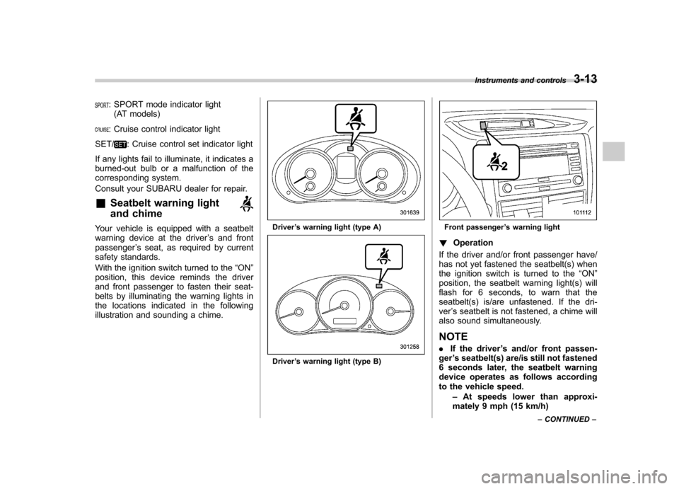
Consult your SUBARU dealer for repair. & Seatbelt warning light
and chime
Your vehicle is equipped with a seatbelt
warning device at the driver ’s and front
passenger ’s seat, as required by current
safety standards.
With the ignition switch turned to the “ON ”
position, this device reminds the driver
and front passenger to fasten their seat-
belts by illuminating the warning lights in
the locations indicated in the following
illustration and sounding a chime.Driver ’s warning light (type A)
Driver ’s warning light (type B)
Front passenger ’s warning light
! Operation
If the driver and/or front passenger have/
has not yet fastened the seatbelt(s) when
the ignition switch is turned to the “ON ”
position, the seatbelt warning light(s) will
flash for 6 seconds, to warn that the
seatbelt(s) is/are unfastened. If the dri-ver ’s seatbelt is not fastened, a chime will
also sound simultaneously. NOTE . If the driver ’s and/or front passen-
ger ’s seatbelt(s) are/is still not fastened
6 seconds later, the seatbelt warning
device operates as follows according
to the vehicle speed.
–At speeds lower than approxi-
mately 9 mph (15 km/h) Instruments and controls
3-13
– CONTINUED –