2013 SUBARU FORESTER brake
[x] Cancel search: brakePage 133 of 436

3-22Instruments and controls
&Vehicle Dynamics
Control warning light/
Vehicle Dynamics Con-
trol operation indicatorlight
!Vehicle Dynamics Control warning light
CAUTION
The Vehicle Dynamics Control sys-
tem provides its ABS control
through the electrical circuit of the
ABS system. Accordingly, if the ABS
is inoperative, the Vehicle Dynamics
Control system becomes unable to
provide ABS control. As a result, the
Vehicle Dynamics Control system
also becomes inoperative, causing
the warning light to illuminate.
Though both the Vehicle Dynamics
Control and ABS systems are inop-
erative in this case, the ordinary
functions of the brake system are
still available. You will be safe while
driving with this condition, but drive
carefully and have your vehicle
checked at a SUBARU dealer as
soon as possible. NOTE .
If the electrical circuit of the Vehicle
Dynamics Control system itself mal-
functions, only this particular warning
light illuminates. Under these circum-
stances, the ABS (Anti-lock Brake
System) remains fully operational.. The warning light illuminates when
the electronic control system of the
ABS/Vehicle Dynamics Control systemmalfunctions.
The Vehicle Dynamics Control system is
probably inoperative under any of the
following conditions. Have your vehicle
checked at a SUBARU dealer immedi-
ately. . The warning light does not illuminate
when the ignition switch is turned to the “ ON ”position.
. The warning light illuminates while the
vehicle is running.
NOTE
If the warning light behavior is as
described in the following examples,
the Vehicle Dynamics Control system
may be considered to be operating
normally. . The warning light illuminates right
after the engine is started but turns off
immediately, remaining off.. The warning light illuminates after the engine has started and turns off
while the vehicle is subsequently beingdriven..
The warning light illuminates during
driving, but it turns off immediately and
remains off. ! Vehicle Dynamics Control opera-
tion indicator light
The indicator light flashes during activa-
tion of the skid suppression function and
during activation of the traction controlfunction. NOTE . The light may remain illuminated for
a short period of time after the engine
has been started, especially in cold
weather. This does not indicate the
existence of a problem. The light
should turn off as soon as the engine
has warmed up.. The indicator light illuminates when
the engine has developed a problem
and the CHECK ENGINE warning light/
malfunction indicator light is on.
The Vehicle Dynamics Control system is
probably malfunctioning under the follow-
ing condition. Have your vehicle checked
at a SUBARU dealer as soon as possible. . The light does not turn off even after
the lapse of several minutes (the engine
Page 141 of 436

3-30Instruments and controls
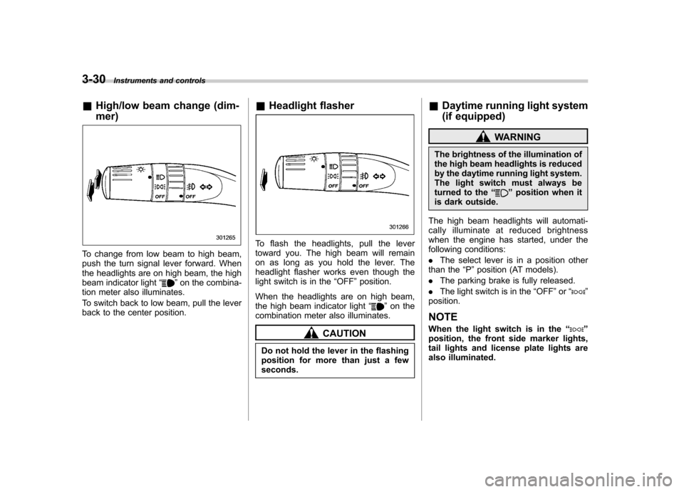
&High/low beam change (dim- mer)
To change from low beam to high beam,
push the turn signal lever forward. When
the headlights are on high beam, the high
beam indicator light “
”on the combina-
tion meter also illuminates.
To switch back to low beam, pull the lever
back to the center position. &
Headlight flasher
To flash the headlights, pull the lever
toward you. The high beam will remain
on as long as you hold the lever. The
headlight flasher works even though the
light switch is in the “OFF ”position.
When the headlights are on high beam,
the high beam indicator light “
”on the
combination meter also illuminates.
CAUTION
Do not hold the lever in the flashing
position for more than just a fewseconds. &
Daytime running light system
(if equipped)
WARNING
The brightness of the illumination of
the high beam headlights is reduced
by the daytime running light system.
The light switch must always be
turned to the “
”position when it
is dark outside.
The high beam headlights will automati-
cally illuminate at reduced brightness
when the engine has started, under the
following conditions: . The select lever is in a position other
than the “P ”position (AT models).
. The parking brake is fully released.
. The light switch is in the “OFF ”or “
”
position.
NOTE
When the light switch is in the “
”
position, the front side marker lights,
tail lights and license plate lights are
also illuminated.
Page 237 of 436

6-8Interior equipment
Cup holders
CAUTION
Take care to avoid spills. Beverages,
if hot, might burn you or your
passengers. Spilled beverages may
also damage upholstery, carpets or
audio equipment.
& Front passenger ’s cup holder
CAUTION
Do not pick up a cup from the cup
holder or put a cup in the holder
while you are driving, as this may
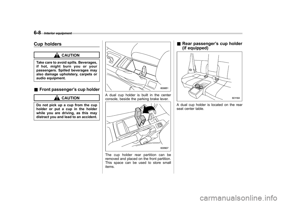
distract you and lead to an accident.A dual cup holder is built in the center
console, beside the parking brake lever.
The cup holder rear partition can be
removed and placed on the front partition.
This space can be used to store smallitems. &
Rear passenger ’s cup holder
(if equipped)
A dual cup holder is located on the rear
seat center table.
Page 239 of 436

6-10Interior equipment
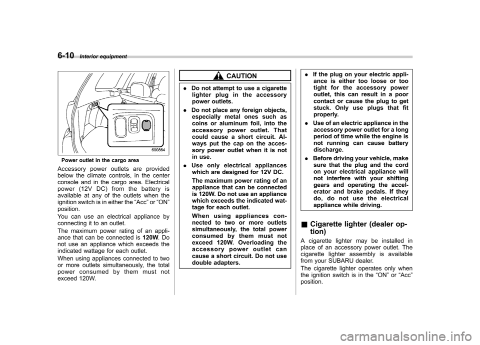
Power outlet in the cargo area
Accessory power outlets are provided
below the climate controls, in the center
console and in the cargo area. Electrical
power (12V DC) from the battery is
available at any of the outlets when the
ignition switch is in either the “Acc ”or “ON ”
position.
You can use an electrical appliance by
connecting it to an outlet.
The maximum power rating of an appli-
ance that can be connected is 120W.Do
not use an appliance which exceeds the
indicated wattage for each outlet.
When using appliances connected to two
or more outlets simultaneously, the total
power consumed by them must not
exceed 120W.
CAUTION
. Do not attempt to use a cigarette
lighter plug in the accessory
power outlets.
. Do not place any foreign objects,
especially metal ones such as
coins or aluminum foil, into the
accessory power outlet. That
could cause a short circuit. Al-
ways put the cap on the acces-
sory power outlet when it is not
in use.
. Use only electrical appliances
which are designed for 12V DC.
The maximum power rating of an
appliance that can be connected
is 120W. Do not use an appliance
which exceeds the indicated wat-
tage for each outlet.
When using appliances con-
nected to two or more outlets
simultaneously, the total power
consumed by them must not
exceed 120W. Overloading the
accessory power outlet can
cause a short circuit. Do not use
double adapters. .
If the plug on your electric appli-
ance is either too loose or too
tight for the accessory power
outlet, this can result in a poor
contact or cause the plug to get
stuck. Only use plugs that fit
properly.
. Use of an electric appliance in the
accessory power outlet for a long
period of time while the engine is
not running can cause batterydischarge.
. Before driving your vehicle, make
sure that the plug and the cord
on your electrical appliance will
not interfere with your shifting
gears and operating the accel-
erator and brake pedals. If they
do, do not use the electrical
appliance while driving.
& Cigarette lighter (dealer op- tion)
A cigarette lighter may be installed in
place of an accessory power outlet. The
cigarette lighter assembly is available
from your SUBARU dealer.
The cigarette lighter operates only when
the ignition switch is in the “ON ”or “Acc ”
position.
Page 252 of 436

Fuel...................................................................... 7-2
Fuel requirements ............................................... 7-2
Fuel filler lid and cap ........................................... 7-3
State emission testing (U.S. only) ...................... 7-6
Preparing to drive ............................................... 7-7
Starting the engine .............................................. 7-7
MT models .......................................................... 7-7
AT models ........................................................... 7-8
Stopping the engine ............................................ 7-9
Remote engine start system (dealer option) ..... 7-9
Starting your vehicle .......................................... 7-10
Remote start safety features ............................... 7-10
Entering the vehicle while it is running via remote start ................................................................. 7-10
Entering the vehicle following remote engine start shutdown ......................................................... 7-10
Pre-heating or pre-cooling the interior of the vehicle ............................................................. 7-11
Service mode ..................................................... 7-11
Remote transmitter programming and programmable feature option ............................ 7-11
System maintenance .......................................... 7-12
Manual transmission .......................................... 7-13
Shifting speeds .................................................. 7-14
Driving tips ........................................................ 7-14
Automatic transmission ..................................... 7-15
Select lever ........................................................ 7-16
Shift lock function .............................................. 7-17
Selection of manual mode .................................. 7-19
Driving tips ........................................................ 7-20 SPORT mode
..................................................... 7-20
Power steering ................................................... 7-21
Braking ............................................................... 7-22
Braking tips ....................................................... 7-22
Brake system .................................................... 7-22
Disc brake pad wear warning indicators ............. 7-23
ABS (Anti-lock Brake System) .......................... 7-23
ABS system self-check ...................................... 7-23
ABS warning light .............................................. 7-23
Electronic Brake Force Distribution (EBD) system ............................................................. 7-24
Steps to take if EBD system malfunctions ..... ..... 7-24
Vehicle Dynamics Control system .................... 7-25
Vehicle Dynamics Control system monitor..... ..... 7-26
Vehicle Dynamics Control OFF switch ................ 7-27
Tire pressure monitoring system (TPMS) (U.S.-spec. models). ........................................ 7-27
Parking your vehicle ......................................... 7-29
Parking brake .................................................... 7-29
Parking tips ....................................................... 7-29
Hill start assist system (MT models) ................ 7-31
Hill start assist warning light .............................. 7-32
Cruise control .................................................... 7-32
To set cruise control .......................................... 7-32
To temporarily cancel the cruise control ............. 7-33
To turn off the cruise control .............................. 7-34
To change the cruising speed .. .......................... 7-34
Cruise control indicator light .............................. 7-35
Cruise control set indicator light ........................ 7-35
Starting and operating
7
Page 258 of 436

The U.S. Environmental Protection
Agency (EPA) and states using two-wheel
dynamometers in their emission testing
program have EXEMPTED SUBARU
AWD vehicles from the portion of the
testing program that involves a two-wheel
dynamometer. There are some states that
use four-wheel dynamometers in their
testing program. When properly used, this
equipment should not damage a SUBARU
AWD vehicle.
Under no circumstances should the rear
wheels be jacked off the ground, nor
should the driveshaft be disconnected for
state emission testing.Preparing to drive
You should perform the following checks
and adjustments every day before you
start driving.
1. Check that all windows, mirrors, and
lights are clean and unobstructed.
2. Check the appearance and condition
of the tires. Also check tires for properinflation.
3. Look under the vehicle for any sign of leaks.
4. Check that the hood and rear gate are
fully closed.
5. Check the adjustment of the seat.
6. Check the adjustment of the inside
and outside mirrors.
7. Fasten your seatbelt. Check that your
passengers have fastened their seatbelts.
8. Check the operation of the warning
and indicator lights when the ignition
switch is turned to the
“ON ”position.
9. Check the gauges, indicator and warn-
ing lights after starting the engine.
NOTE
Engine oil, engine coolant, brake fluid,
washer fluid and other fluid levels
should be checked daily, weekly or at
fuel stops. Starting the engine
CAUTION
Do not operate the starter motor
continuously for more than 10 sec-
onds. If the engine fails to start after
operating the starter for 5 to 10
seconds, wait for 10 seconds or
more before trying again.
NOTE
It may be difficult to start the engine
when the battery has been discon-
nected and reconnected (for mainte-
nance or other purposes). This diffi-
culty is caused by the electronically
controlled throttle ’s self-diagnosis
function. To overcome it, keep the
ignition switch in the “ON ”position
for approximately 10 seconds before
starting the engine. & MT models
1. Apply the parking brake.
2. Turn off unnecessary lights and ac- cessories.
3. Depress the clutch pedal to the floor
and shift the shift lever into neutral. Hold
the clutch pedal to the floor while starting Starting and operating
7-7
– CONTINUED –
Page 259 of 436

7-8Starting and operating
the engine. The starter motor will only
operate when the clutch pedal is pressed
fully to the floor.
4. Turn the ignition switch to the “ON ”
position and check the operation of the
warning and indicator lights. Refer to“ Warning and indicator lights ”F 3-12.
5. Turn the ignition switch to the “START ”
position without depressing the accelera-
tor pedal. Release the key immediately
after the engine has started.
If the engine does not start, perform the
following procedure.
(1) Turn the ignition switch to the“LOCK ”position and wait for at least
10 seconds. After checking that the
parking brake is firmly applied, turn the
ignition switch to the “START ”position
while depressing the accelerator pedal
slightly (approximately a quarter of the
full stroke). Release the accelerator
pedal as soon as the engine starts.
(2) If this fails to start the engine, turn
the ignition switch back to the “LOCK ”
position and wait for at least 10
seconds. Then fully depress the accel-
erator pedal and turn the ignition
switch to the “START ”position. If the
engine starts, quickly release the
accelerator pedal.
(3) If this does not start the engine,
turn the ignition switch again to the “
LOCK ”position. After waiting for 10
seconds or longer, turn the ignition
switch to the “START ”position without
depressing the accelerator pedal.
(4) If the engine still does not start,
contact your nearest SUBARU dealer
for assistance.
6. Confirm that all warning and indicator
lights have turned off after the engine has
started. The fuel injection system auto-
matically lowers the idle speed as the
engine warms up.
& AT models
1. Apply the parking brake.
2. Turn off unnecessary lights and ac- cessories.
3. Shift the select lever to the “P ” or “N ”
position (preferably “P ”position).
The starter motor will only operate when
the select lever is at the “P ”or “N ”position.
4. Turn the ignition switch to the “ON ”
position and check the operation of the
warning and indicator lights. Refer to “ Warning and indicator lights ”F 3-12.
5. Turn the ignition switch to the “START ”
position without depressing the accelera-
tor pedal. Release the key immediately
after the engine has started.
If the engine does not start, perform the following procedure.
(1) Turn the ignition switch to the “LOCK ”position and wait for at least
10 seconds. After checking that the
parking brake is firmly applied, turn the
ignition switch to the “START ”position
while depressing the accelerator pedal
slightly (approximately a quarter of the
full stroke). Release the accelerator
pedal as soon as the engine starts.
(2) If this fails to start the engine, turn
the ignition switch back to the “LOCK ”
position and wait for at least 10
seconds. Then fully depress the accel-
erator pedal and turn the ignition
switch to the “START ”position. If the
engine starts, quickly release the
accelerator pedal.
(3) If this does not start the engine,
turn the ignition switch again to the“ LOCK ”position. After waiting for 10
seconds or longer, turn the ignition
switch to the “START ”position without
depressing the accelerator pedal.
(4) If the engine still does not start,
contact your nearest SUBARU dealer
for assistance.
6. Confirm that all warning and indicator
lights have turned off after the engine has
started. The fuel injection system auto-
matically lowers the idle speed as the
engine warms up.
Page 260 of 436

While the engine is warming up, make
sure that the select lever is at the“P ” or
“ N ”position and that the parking brake is
applied.
CAUTION
If you need to restart the engine
while the vehicle is moving, shift the
select lever into the “N ” position. Do
not attempt to place the select lever
of a moving vehicle into the “P ”
position. Stopping the engine
The ignition switch should be turned off
only when the vehicle is stopped and the
engine is idling.
WARNING
Do not stop the engine when the
vehicle is moving. This will cause
loss of power to the power steering
and the brake booster, making steer-
ing and braking more difficult. It
could also result in accidental acti-
vation of the steering lock, causing
the steering wheel to lock. Remote engine start system
(dealer option)
WARNING
. Do not remote start a vehicle in
an enclosed environment (e.g., in
a closed garage). Prolonged op-
eration of a motor vehicle in an
enclosed environment can cause
a harmful build-up of Carbon
Monoxide. Carbon Monoxide is
harmful to your health. Exposure
to high levels of Carbon Monox-
ide can cause headaches, dizzi-
ness or in extreme cases uncon-
sciousness and/or death.
. Before performing any servicing
of the vehicle, temporarily place
the remote engine start system in
service mode to prevent the
system from unexpectedly start-
ing the engine. Starting and operating
7-9
– CONTINUED –