Page 168 of 484
168
2-1. Driving procedures
CAUTION
■To prevent battery discharge
●Do not leave the push-button ignition switch in “ACC” or “ON” mode for
long periods of time without the engine running.
●If the keyless access with push button start system indicator light (green)
is illuminated, the push-button ignition switch is not off. When exiting the
vehicle, always check that the push-button ignition switch is off.
●Vehicles with an automatic transmission: Do not stop the engine when the
select lever is in a position other than P. If the engine is stopped in another
select lever position, the push-button ignition switch will not be turned off
but instead be turned to “ACC” mode. If the vehicle is left in “ACC” mode,
battery discharge may occur.
■When starting the engine
●Do not race a cold engine.
●If the engine becomes difficult to start or stalls frequently, have your vehi-
cle checked by your SUBARU dealer immediately.
■Symptoms indicating a malfunction with the push-button ignition
switch
If the push-button ignition switch seems to be operating somewhat differently
than usual, such as the switch sticking slightly, there may be a malfunction.
Contact your SUBARU dealer immediately.
Page 170 of 484
170
2-1. Driving procedures
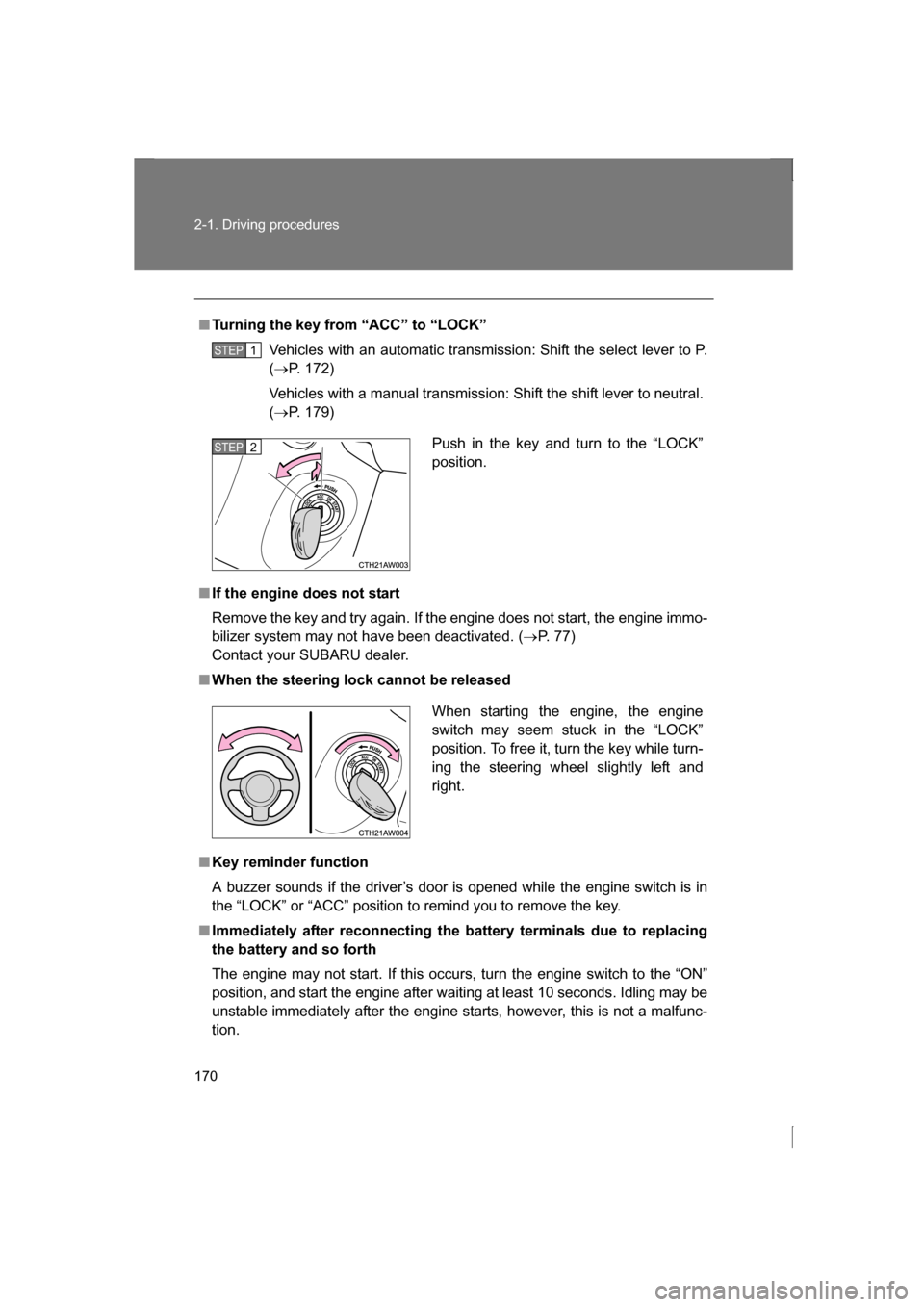
■Turning the key from “ACC” to “LOCK”Vehicles with an automatic transmission: Shift the select lever to P. (→ P. 172)
Vehicles with a manual transmission: Shift the shift lever to neutral. ( → P. 179)
■If the engine does not start
Remove the key and try again. If the engine does not start, the engine immo-
bilizer system may not have been deactivated. ( →P. 77)
Contact your SUBARU dealer.
■When the steering lock cannot be released
■Key reminder function
A buzzer sounds if the driver’s door is opened while the engine switch is in
the “LOCK” or “ACC” position to remind you to remove the key.
■Immediately after reconnecting the battery terminals due to replacing
the battery and so forth
The engine may not start. If this occurs, turn the engine switch to the “ON”
position, and start the engine after waiting at least 10 seconds. Idling may be
unstable immediately after the engine starts, however, this is not a malfunc-
tion.
STEP 1
Push in the key and turn to the “LOCK”
position.STEP 2
When starting the engine, the engine
switch may seem stuck in the “LOCK”
position. To free it, turn the key while turn-
ing the steering wheel slightly left andright.
Page 175 of 484
175
2-1. Driving procedures
2
When driving
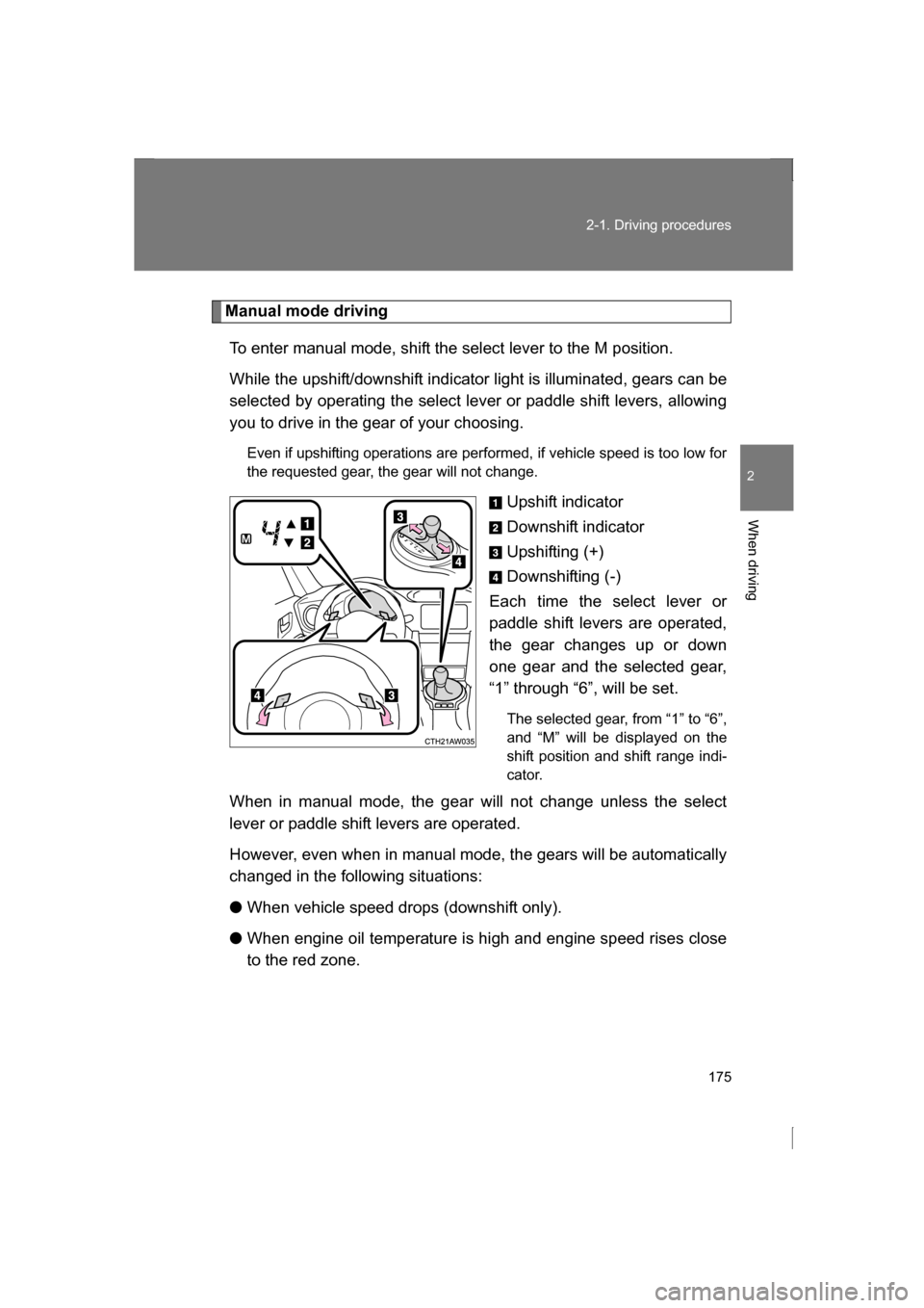
Manual mode drivingTo enter manual mode, shift the select lever to the M position.
While the upshift/downshift indicator light is illuminated, gears can be
selected by operating the select lever or paddle shift levers, allowing
you to drive in the gear of your choosing. Even if upshifting operations are performed, if vehicle speed is too low for
the requested gear, the gear will not change.
Upshift indicator
Downshift indicator
Upshifting (+)
Downshifting (-)
Each time the select lever or
paddle shift levers are operated,
the gear changes up or down
one gear and the selected gear,
“1” through “6”, will be set.
The selected gear, from “1” to “6”,
and “M” will be displayed on the
shift position and shift range indi-
cator.
When in manual mode, the gear will not change unless the select
lever or paddle shift levers are operated.
However, even when in manual mode, the gears will be automatically
changed in the following situations: ● When vehicle speed drops (downshift only).
● When engine oil temperature is high and engine speed rises close
to the red zone.
Page 182 of 484
182
2-1. Driving procedures
Turn signal lever
■Turn signals can be operated when
Vehicles without a keyless access with push button start system
The engine switch is in the “ON” position.
Vehicles with a keyless access with push button start system
The push-button ignition switch is in “ON” mode.
■If the indicators flash faster than usual
Check that a light bulb in the turn signal lights has not burned out.
The turn signal lever can be used to show the following intentions of
the driver:
Right turn
Left turn
Lane change to the right
(push and hold the lever
partway)
The right hand signals will
flash until you release the
lever.
Lane change to the left
(push and hold the lever
partway)
The left hand signals will flash
until you release the lever.
Page 183 of 484
183
2-1. Driving procedures
2
When driving
Parking brake
■Usage in winter time
→P. 226
CAUTION
■Before driving
Fully release the parking brake.
Driving the vehicle with the parking brake set will lead to brake components
overheating, which may affect braking performance and increase brake
wear.
To set the parking brake, fully pull the parking brake lever while
depressing the brake pedal.
To release the parking brake, slightly raise the lever and lower it
completely while pressing the button.
U.S.A. Canada
Page 189 of 484
189
2-2. Instrument cluster
2
When driving
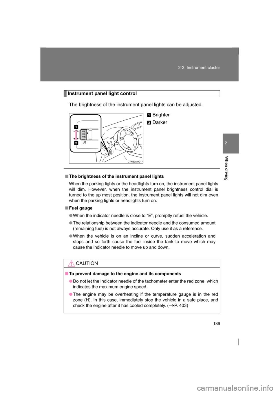
Instrument panel light controlThe brightness of the instrument panel lights can be adjusted. Brighter
Darker
■The brightness of the instrument panel lights
When the parking lights or the headlights turn on, the instrument panel lights
will dim. However, when the instrument panel brightness control dial is
turned to the up most position, the instrument panel lights will not dim even
when the parking lights or headlights turn on.
■Fuel gauge
●When the indicator needle is close to “E”, promptly refuel the vehicle.
●The relationship between the indicator needle and the consumed amount
(remaining fuel) is not always accurate. Only use it as a reference.
●When the vehicle is on an incline or curve, sudden acceleration and
stops and so forth cause the fuel inside the tank to move which may
cause the indicator needle to move up and down.
CAUTION
■To prevent damage to the engine and its components
●Do not let the indicator needle of the tachometer enter the red zone, which
indicates the maximum engine speed.
●The engine may be overheating if the temperature gauge is in the red
zone (H). In this case, immediately stop the vehicle in a safe place, and
check the engine after it has cooled completely. ( →P. 403)
Page 190 of 484
190
2-2. Instrument cluster
Indicators and war ning lights
The indicator and warning lights on the instrument cluster and cen-
ter panel inform the driver of the status of the vehicle’s various sys-
tems.
For the purpose of explanation, the following illustration displays all
indicators and warning lights illuminated.
Instrument cluster
Center panel
Page 191 of 484
191
2-2. Instrument cluster
2
When driving
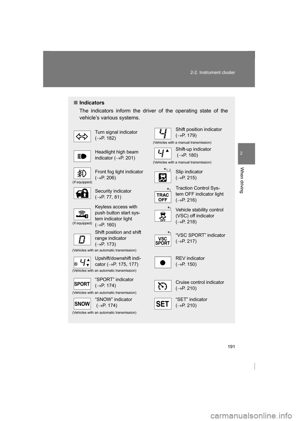
■Indicators
The indicators inform the driver of the operating state of the
vehicle’s various systems.
Turn signal indicator (→ P. 182)Shift position indicator (→ P. 179)
(Vehicles with a manual transmission)
Headlight high beam
indicator ( →P. 201)Shift-up indicator (→ P. 180)
(Vehicles with a manual transmission)
(If equipped)
Front fog light indicator (→ P. 206)Slip indicator (→ P. 215)
Security indicator (→ P. 77, 81)Traction Control Sys-
tem OFF indicator light (→ P. 216)
(If equipped)
Keyless access with
push button start sys-
tem indicator light (→ P. 160)Vehicle stability control
(VSC) off indicator (→ P. 218)
Shift position and shift
range indicator (→ P. 173)“VSC SPORT” indicator (→ P. 217)
(Vehicles with an automatic transmission)
Upshift/downshift indi-
cator ( →P. 175, 177)REV indicator (→ P. 150)
(Vehicles with an automatic transmission)
“SPORT” indicator (→ P. 174)Cruise control indicator (→ P. 210)
(Vehicles with an automatic transmission)
“SNOW” indicator (→ P. 174)“SET” indicator (→ P. 210)
(Vehicles with an automatic transmission)
*1, 2
*
1
*1
*
1