Page 665 of 796
09-194891-01
4) ARP (Active Roll-Over Protection)
The ARP (Active Roll-over Protection) system is a safety assistant device that minimizes, by controlling
brakes and the engine, the physical tendency of the vehicle rollover during sharp lane changes or U-
turns. For the system, software is added to the existing ESP system and no additional device or switch
is needed. One must note that the ARP system, just as general assistant devices including the ABS, is
only a safety assistant device using the ESP system and its function is useless when the situation
overcomes the physical power. Following picture shows how the ARP compensates the vehicle
position by varying each wheel's braking power to overcome the physical tendency of the vehicle
rollover during sharp turns.
The vehicle driving condition is controlled by the internally programmed logic according to the input
signals from wheel speed sensor, steering angle sensor and lateral sensor.
Page 667 of 796

09-214891-01
4. SCHEMATIC DIAGRAM
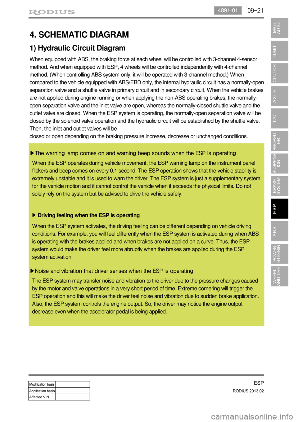
When equipped with ABS, the braking force at each wheel will be controlled with 3-channel 4-sensor
method. And when equipped with ESP, 4 wheels will be controlled independently with 4-channel
method. (When controlling ABS system only, it will be operated with 3-channel method.) When
compared to the vehicle equipped with ABS/EBD only, the internal hydraulic circuit has a normally-open
separation valve and a shuttle valve in primary circuit and in secondary circuit. When the vehicle brakes
are not applied during engine running or when applying the non-ABS operating brakes, the normally-
open separation valve and the inlet valve are open, whereas the normally-closed shuttle valve and the
outlet valve are closed. When the ESP system is operating, the normally-open separation valve will be
closed by the solenoid valve operation and the hydraulic circuit will be established by the shuttle valve.
Then, the inlet and outlet valves will be
closed or open depending on the braking pressure increase, decrease or unchanged conditions.
▶The warning lamp comes on and warning beep sounds when the ESP is operating
Driving feeling when the ESP is operating ▶
▶Noise and vibration that driver senses when the ESP is operating
1) Hydraulic Circuit Diagram
When the ESP operates during vehicle movement, the ESP warning lamp on the instrument panel
flickers and beep comes on every 0.1 second. The ESP operation shows that the vehicle stability is
extremely unstable and it is used to warn the driver. The ESP system is just a supplementary system
for the vehicle motion and it cannot control the vehicle when it exceeds the physical limits. Do not
solely rely on the system but be advised to drive the vehicle safely.
When the ESP system activates, the driving feeling can be different depending on vehicle driving
conditions. For example, you will feel differently when the ESP system is activated during when ABS
is operating with the brakes applied and when brakes are not applied on a curve. Thus, the ESP
system would make the driver feel more abruptly when the brakes are applied during the ESP
system activation.
The ESP system may transfer noise and vibration to the driver due to the pressure changes caused
by the motor and valve operations in a very short period of time. Extreme cornering will trigger the
ESP operation and this will make the driver feel noise and vibration due to sudden brake application.
Also, the ESP system controls the engine output. So, the driver may notice the engine output
decrease even when the accelerator pedal is being applied.
Page 669 of 796
09-234891-01
(2) Hydraulic Circuit of HBA
The above figure shows one front and one rear wheel and the same hydraulic circuit forms as in the
ESP operation. When HECU recognizes that it is an emergency and it is required for hard braking,
depending on the pressure value of the brake pressure sensor and pressure changes caused by the
pressure sensor timing, it operates the pump immediately to apply the brake pressure at the wheels.
Then, the pressure in the pump increases until just before the corresponding wheel gets locked. The
motor still keeps rotating and the outlet valve and the separation valve will stay closed. When the wheel
starts to lock, the HBA function cancels and switches to ABS operation.
Page 683 of 796

10-10
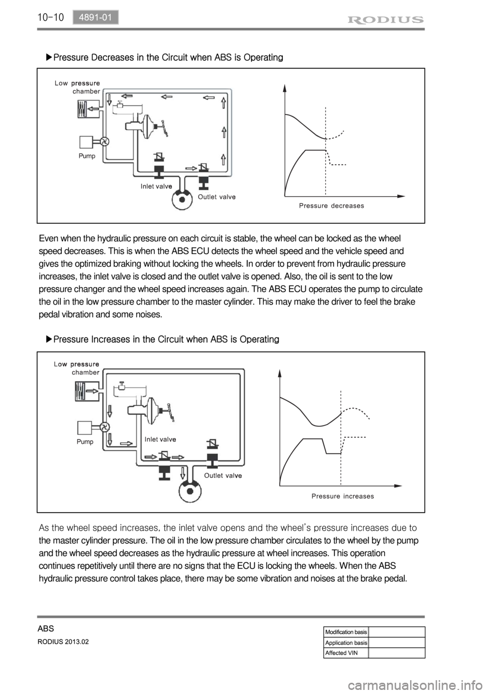
▶Pressure Decreases in the Circuit when ABS is Operating
Even when the hydraulic pressure on each circuit is stable, the wheel can be locked as the wheel
speed decreases. This is when the ABS ECU detects the wheel speed and the vehicle speed and
gives the optimized braking without locking the wheels. In order to prevent from hydraulic pressure
increases, the inlet valve is closed and the outlet valve is opened. Also, the oil is sent to the low
pressure changer and the wheel speed increases again. The ABS ECU operates the pump to circulate
the oil in the low pressure chamber to the master cylinder. This may make the driver to feel the brake
pedal vibration and some noises.
▶Pressure Increases in the Circuit when ABS is Operating
As the wheel speed increases, the inlet valve opens and the wheel’s pressure increases due to
the master cylinder pressure. The oil in the low pressure chamber circulates to the wheel by the pump
and the wheel speed decreases as the hydraulic pressure at wheel increases. This operation
continues repetitively until there are no signs that the ECU is locking the wheels. When the ABS
hydraulic pressure control takes place, there may be some vibration and noises at the brake pedal.
Page 686 of 796
11-4
Steering column shaft assembly
Steering column shat assembly mounting bracket changed due to change of multifunction switch
Steering wheel body and heating system
Heating controller added due to newly adopted steering wheel heating system
2. CHANGES IN STEERING SYSTEM
Steering wheel heating switch
Heated wire used in steering wheel switch
(option)
Heating controller
Mounting bracket
Page 691 of 796

11-94610-00
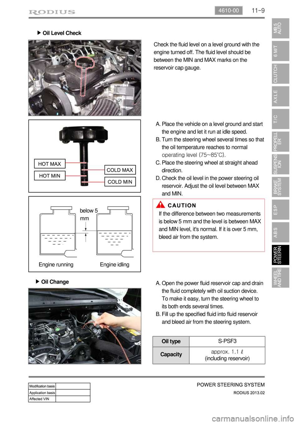
Oil Level Check ▶
Check the fluid level on a level ground with the
engine turned off. The fluid level should be
between the MIN and MAX marks on the
reservoir cap gauge.
Place the vehicle on a level ground and start
the engine and let it run at idle speed.
Turn the steering wheel several times so that
the oil temperature reaches to normal
operating level (75~85˚C).
Place the steering wheel at straight ahead
direction.
Check the oil level in the power steering oil
reservoir. Adjust the oil level between MAX
and MIN. A.
B.
C.
D.
Oil Change ▶
If the difference between two measurements
is below 5 mm and the level is between MAX
and MIN level, it's normal. If it is over 5 mm,
bleed air from the system.
Open the power fluid reservoir cap and drain
the fluid completely with oil suction device.
To make it easy, turn the steering wheel to
its both ends several times.
Fill up the specified fluid into fluid reservoir
and bleed air from the steering system. A.
B.
Oil typeS-PSF3
Capacityapprox. 1.1 ℓ
(including reservoir)
below 5
mm
Engine running Engine idling
Page 699 of 796
12-4
Spare Tire & Winch Assembly
- Spare tire specification added (same as one fitted to vehicle with standard wheel and tire)
Wheel assembly
16 inch (6.5JX16) 17 inch (7.0JX17)
2WD 4WD 2WD 4WD
225/65R16 235/60R17
- 16 inch wheel design changed (same as before for tire size)
- 17 inch wheel specification added (235/60R17 tire)
2. CHANGES
Wheel tire design changed and specification added ▶
With spare tire ▶
Spare tire
Winch assembly
Page 793 of 796
06-70000-00
Spoiler assembly
Spoiler design changed
Front
Front bumper fascia change results in installation design change
Rear
Changed from split type to integral type
Wheel house cover
Page:
< prev 1-8 9-16 17-24