Page 522 of 751

04-6
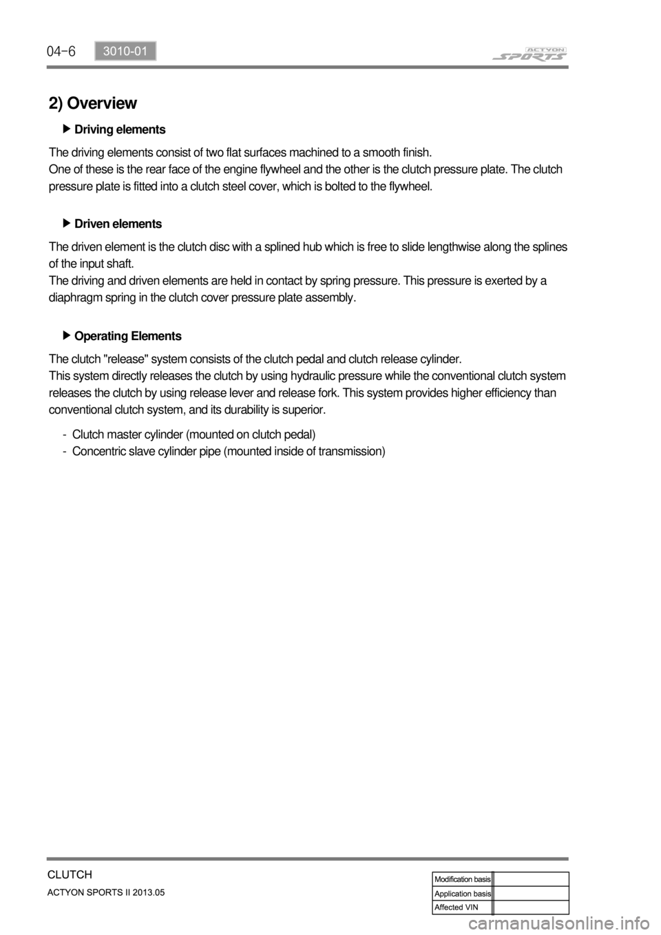
2) Overview
Driving elements ▶
The driving elements consist of two flat surfaces machined to a smooth finish.
One of these is the rear face of the engine flywheel and the other is the clutch pressure plate. The clutch
pressure plate is fitted into a clutch steel cover, which is bolted to the flywheel.
Driven elements ▶
The driven element is the clutch disc with a splined hub which is free to slide lengthwise along the splines
of the input shaft.
The driving and driven elements are held in contact by spring pressure. This pressure is exerted by a
diaphragm spring in the clutch cover pressure plate assembly.
Operating Elements ▶
The clutch "release" system consists of the clutch pedal and clutch release cylinder.
This system directly releases the clutch by using hydraulic pressure while the conventional clutch system
releases the clutch by using release lever and release fork. This system provides higher efficiency than
conventional clutch system, and its durability is superior.
Clutch master cylinder (mounted on clutch pedal)
Concentric slave cylinder pipe (mounted inside of transmission) -
-
Page 558 of 751
09-94850-01
Problem Cause Action
Burning smell around
tireToo frequent braking in high driving speed Reduce the use of
foot brake/use
engine brake
properly Used only foot brake during downhill driving
Driving with foot on brake pedal Get off the foot from
pedal
Foreign materials such as dirt or sand in brake system Replace: caliper,
wheel cylinder,
master cylinder,
return spring
Broken return spring in shoe assembly Replace
Incorrectly adjusted parking brake cable Adjust
Incorrect wheel or wheel cover
(generating the heat)Replace
Page 563 of 751
09-14
Specified value (B)155mm
Push rod
Stop lamp
switch Pedal Height ▶
Check the pedal height with below procedures: -
Start the engine and measure the length (A)
between floor mat and pedal.
If the measured value is out of the specified
value, adjust the length. 1.
2.
Adjust the pedal height with below procedures: -
Disconnect the stop lamp switch connector.
Unscrew the lock nut and remove the stop
lamp switch assembly.
Loosen the lock nut on the pedal push rod.
Turn the pedal push rod to adjust the pedal
height.
Tighten the lock nut.
Install the stop lamp switch assembly.
Connect the stop lamp switch connector.
Check if the stop lamps come on when
pressing the brake pedal around 5 mm.
If the stop lamp dpes not come on, adjust the
stop lamp switch assembly again.
If the stop lamps come on, tighten the lock nut
and measure the pedal height again. 1.
2.
3.
4.
5.
6.
7.
8.
9.
10.
Page 589 of 751
10-94892-01
Front wheel speed sensor
(4WD)
Located on the hub assembly.
Front discFront caliper assembly
(2WD/4WD)
Located on the knuckle.
ABS hydraulic device and control unit
Located near the brake booster in engine compartment.
Page 611 of 751
11-94890-10
ESP OFF switch
Located on the left side of
instrument panel.
Rear wheel speed sensor
Located on the both ends of
rear axle.Front wheel speed sensor
Located on the hub assembly.Sensor cluster
Located at the bottom of center
fascia panel.
Steering wheel angle sensor
Located on column shaft with
contact coil.HECU assembly
Located near the brake booster
in engine compartment and
contains the pressure sensor.
2. COMPONENTS
Page 738 of 751

04-37340-00
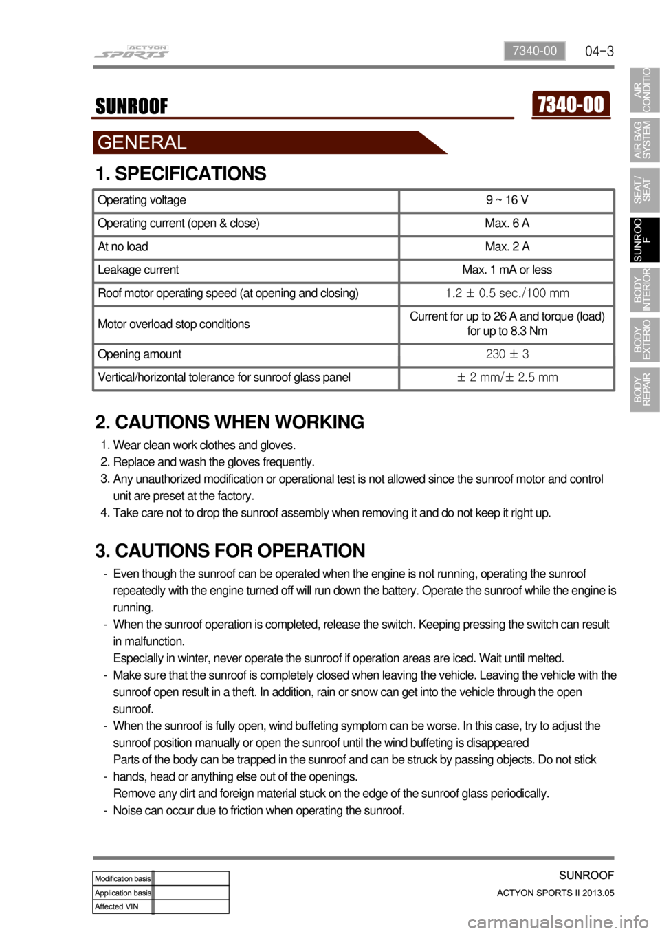
1. SPECIFICATIONS
2. CAUTIONS WHEN WORKING
Wear clean work clothes and gloves.
Replace and wash the gloves frequently.
Any unauthorized modification or operational test is not allowed since the sunroof motor and control
unit are preset at the factory.
Take care not to drop the sunroof assembly when removing it and do not keep it right up. 1.
2.
3.
4.
Operating voltage 9 ~ 16 V
Operating current (open & close) Max. 6 A
At no load Max. 2 A
Leakage current Max. 1 mA or less
Roof motor operating speed (at opening and closing)1.2 ± 0.5 sec./100 mm
Motor overload stop conditionsCurrent for up to 26 A and torque (load)
for up to 8.3 Nm
Opening amount230 ± 3
Vertical/horizontal tolerance for sunroof glass panel± 2 mm/± 2.5 mm
3. CAUTIONS FOR OPERATION
Even though the sunroof can be operated when the engine is not running, operating the sunroof
repeatedly with the engine turned off will run down the battery. Operate the sunroof while the engine is
running.
When the sunroof operation is completed, release the switch. Keeping pressing the switch can result
in malfunction.
Especially in winter, never operate the sunroof if operation areas are iced. Wait until melted.
Make sure that the sunroof is completely closed when leaving the vehicle. Leaving the vehicle with the
sunroof open result in a theft. In addition, rain or snow can get into the vehicle through the open
sunroof.
When the sunroof is fully open, wind buffeting symptom can be worse. In this case, try to adjust the
sunroof position manually or open the sunroof until the wind buffeting is disappeared
Parts of the body can be trapped in the sunroof and can be struck by passing objects. Do not stick
hands, head or anything else out of the openings.
Remove any dirt and foreign material stuck on the edge of the sunroof glass periodically.
Noise can occur due to friction when operating the sunroof. -
-
-
-
-
-
Page:
< prev 1-8 9-16 17-24