Page 872 of 1336
8510-00
Multifunction wiper switches
2) Multifunction Switch
Multifunction light switches
Light switch
Front wiper switch
Wiper speed dial
Rear wiper switch Front fog lamp switch
Front auto washer switch The multifunction switch contains the auto washer and wiper switch, front fog lamp switch and auto
hazard warning flasher switch. For the vehicle with air bag, since the contact coil is fitted to the upper part
of the multifunction switch and ESP steering wheel angle sensor is fitted to upper part of the contact coil,
pay attention to when removing and fitting or checking the wiring.
Page 1058 of 1336
3190-01
1) Characteristics of WM6F1 M/T
Both Forward and Reverse gears use the helical gear and are made of high-strength material.
Drives the clutch with a concentric slave cylinder mounting bolt.
Shifting the transmission gears is performed through the remote control cable.
A pull type clutch is used for Reverse gear shifting.
Features triple/double/single synchronization. -
-
-
-
-
Clutch housing
Transmission case
Input shaft
Concentric slave cylinder
Shift lever
Selector lever
Wiring bracket
Neutral switch
Backup lamp switch
Reverse idle shaft mounting bolt 1.
2.
3.
4.
5.
6.
7.
8.
9.
10.Control guide bolt
Oil filler plug (for servicing)
Oil drain plug
Oil filler plug (for manufacturing)
Air breather
Detent pin (for securing shift fork)
Oil seal (RH)
Oil seal (LH)
Control housing 11.
12.
13.
14.
15.
16.
17.
18.
19.
Page 1222 of 1336
2) Control Condition For PTC Heater
Operation Operating condition PTC heater status
HI mode operation
(PTC2, 3)PTC heater operates in
"HIGH" mode if operating
conditions are met
LO mode operation
(PTC1)PTC heater operates in
"LOW" mode if operating
conditions are met
Conditions for
deactivating
Air conditioner blower switch OFF
When the ambient temperature sensor is
faulty (short or open circuit in the wiring)
Engine is cranking
Battery voltage is 11 V or less
Glow plug is being preheated (Glow indicator
comes on) -
-
-
-
-
-
-
-
-
Conditions for PTC heater "LOW" operation mode (2nd step)
Page 1237 of 1336

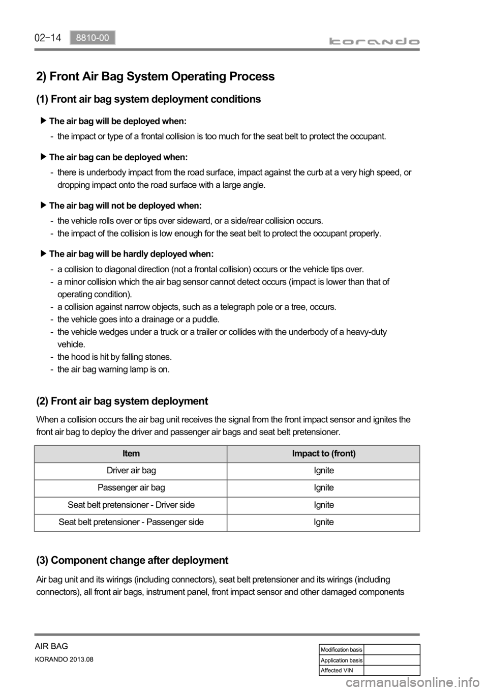
The air bag will be deployed when:
The air bag can be deployed when:
the impact or type of a frontal collision is too much for the seat belt to protect the occupant. -
a collision to diagonal direction (not a frontal collision) occurs or the vehicle tips over.
a minor collision which the air bag sensor cannot detect occurs (impact is lower than that of
operating condition).
a collision against narrow objects, such as a telegraph pole or a tree, occurs.
the vehicle goes into a drainage or a puddle.
the vehicle wedges under a truck or a trailer or collides with the underbody of a heavy-duty
vehicle.
the hood is hit by falling stones.
the air bag warning lamp is on. -
-
-
-
-
-
-the vehicle rolls over or tips over sideward, or a side/rear collision occurs.
the impact of the collision is low enough for the seat belt to protect the occupant properly. -
-
The air bag will be hardly deployed when:
2) Front Air Bag System Operating Process
(1) Front air bag system deployment conditions
there is underbody impact from the road surface, impact against the curb at a very high speed, or
dropping impact onto the road surface with a large angle. -
The air bag will not be deployed when:
(2) Front air bag system deployment
When a collision occurs the air bag unit receives the signal from the front impact sensor and ignites the
front air bag to deploy the driver and passenger air bags and seat belt pretensioner.
Item Impact to (front)
Driver air bag Ignite
Passenger air bag Ignite
Seat belt pretensioner - Driver side Ignite
Seat belt pretensioner - Passenger side Ignite
(3) Component change after deployment
Air bag unit and its wirings (including connectors), seat belt pretensioner and its wirings (including
connectors), all front air bags, instrument panel, front impact sensor and other damaged components
Page 1239 of 1336

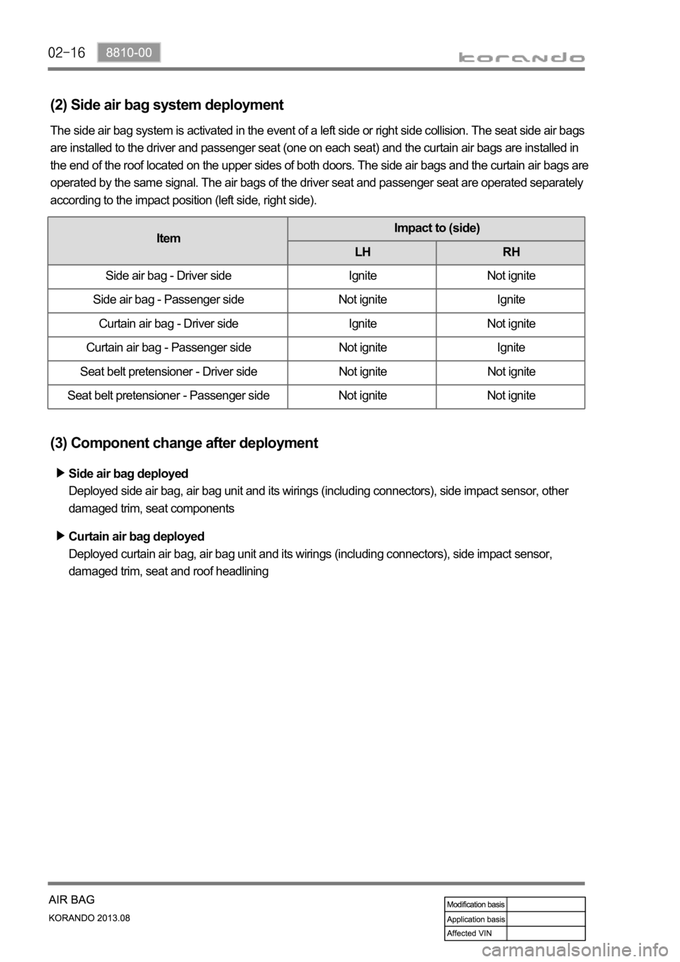
(2) Side air bag system deployment
The side air bag system is activated in the event of a left side or right side collision. The seat side air bags
are installed to the driver and passenger seat (one on each seat) and the curtain air bags are installed in
the end of the roof located on the upper sides of both doors. The side air bags and the curtain air bags are
operated by the same signal. The air bags of the driver seat and passenger seat are operated separately
according to the impact position (left side, right side).
ItemImpact to (side)
LH RH
Side air bag - Driver side Ignite Not ignite
Side air bag - Passenger side Not ignite Ignite
Curtain air bag - Driver side Ignite Not ignite
Curtain air bag - Passenger side Not ignite Ignite
Seat belt pretensioner - Driver side Not ignite Not ignite
Seat belt pretensioner - Passenger side Not ignite Not ignite
(3) Component change after deployment
Side air bag deployed
Deployed side air bag, air bag unit and its wirings (including connectors), side impact sensor, other
damaged trim, seat components
Curtain air bag deployed
Deployed curtain air bag, air bag unit and its wirings (including connectors), side impact sensor,
damaged trim, seat and roof headlining
Page 1251 of 1336

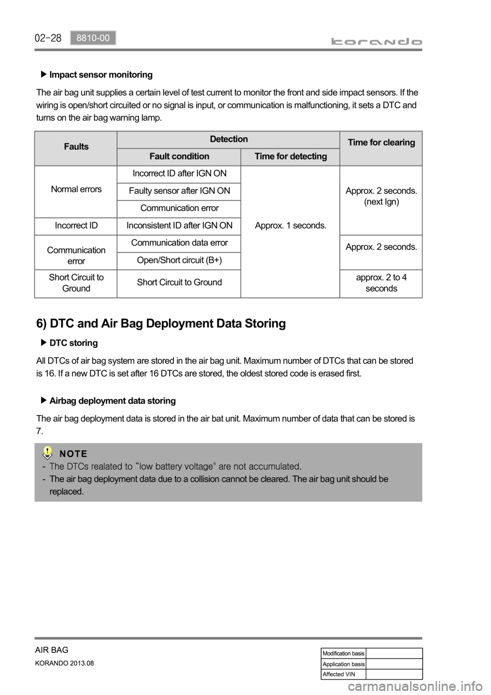
Impact sensor monitoring
The air bag unit supplies a certain level of test current to monitor the front and side impact sensors. If the
wiring is open/short circuited or no signal is input, or communication is malfunctioning, it sets a DTC and
turns on the air bag warning lamp.
FaultsDetection
Time for clearing
Fault condition Time for detecting
Normal errorsIncorrect ID after IGN ON
Approx. 1 seconds.Approx. 2 seconds.
(next Ign) Faulty sensor after IGN ON
Communication error
Incorrect ID Inconsistent ID after IGN ON
Communication
errorCommunication data error
Approx. 2 seconds.
Open/Short circuit (B+)
Short Circuit to
GroundShort Circuit to Groundapprox. 2 to 4
seconds
6) DTC and Air Bag Deployment Data Storing
DTC storing
Airbag deployment data storing
The air bag deployment data due to a collision cannot be cleared. The air bag unit should be
replaced. -
- All DTCs of air bag system are stored in the air bag unit. Maximum number of DTCs that can be stored
is 16. If a new DTC is set after 16 DTCs are stored, the oldest stored code is erased first.
The air bag deployment data is stored in the air bat unit. Maximum number of data that can be stored is
7.
Page 1275 of 1336
(3) Connector pin description
Seat heated wire and
ventilation unit side
Seat heated wire and
ventilation unit wiring side Pin No. Function
1IGN2
2-
3-
4 Ventilation switch
5 Heater switch (LH)
6 Heater switch (RH)
7 Heater level 1 (LH)
8 Heater level 1 (RH)
9 Ventilation level 1 (LH)
10 Heater back (LH) NTC -
11 Heater back (RH) NTC +
12 Cushion ventilation power (+)
13 Heater back (LH) HTR
14 ALT
15 -
16 -
17 -
18 -
19 -
20 Heater level 2 (LH)
21 Heater level 2 (RH)
22 Ventilation level 2 (LH)
23 Heater back (LH) NTC +
24 Heater back (RH) NTC -
25 Heater back (RH) HTR
26 Ground