2013 SSANGYONG KORANDO engine
[x] Cancel search: enginePage 980 of 1336

Ensure that the connection or disconnection between the audio system and the USB memory/iPod
is carried out only when the engine is switched off. If the engine is switched on or off while the USB
memory is connected or disconnected, the USB memory may be damaged or not operate normally.
The audio system may not recognize some USB memory depending on the comparability or
condition. Check whether the USB memory operates normally in the vehicle before using it.
Take great care to ensure that the USB connection does not come in contact with the human body
or any object and the USB linking cable does not disturb a safe driving.
When you connect and disconnect the USB memory to the audio system several times in a short
periods, it may cause the USB memory to corrupt. If you particularly disconnect USB memory
during playback, it may be broken or operate incorrectly.
When you use the USB device for charging or heating by using the USB terminal on the audio
system, it may cause the system to deteriorate or fail.
iPod is a registered trademark of Apple Inc.
This audio system supports only the following iPod products: iPod Nano /iPod/iPod Touch/ iPhone.
This audio system may not support some iPod/iPhone products.
Always use the linking cable included with the iPod product when connecting it to the audio system.
The other cables may not be compatible and cause the audio system to fail.
In some cases, the iPod product may be damaged or not operate normally when the engine is
switched on while it is connected to the audio system. When not in use, always disconnect the iPod
product with the engine switched off.
When you use the iPod by connecting it to the audio system, the playback function and information
display may differ from original.
The iPod product can't be recharged using a iPod linking cable. -
-
-
-
-
-
-
-
-
-
-
-Cautions for using USB memory/iPod
Page 984 of 1336
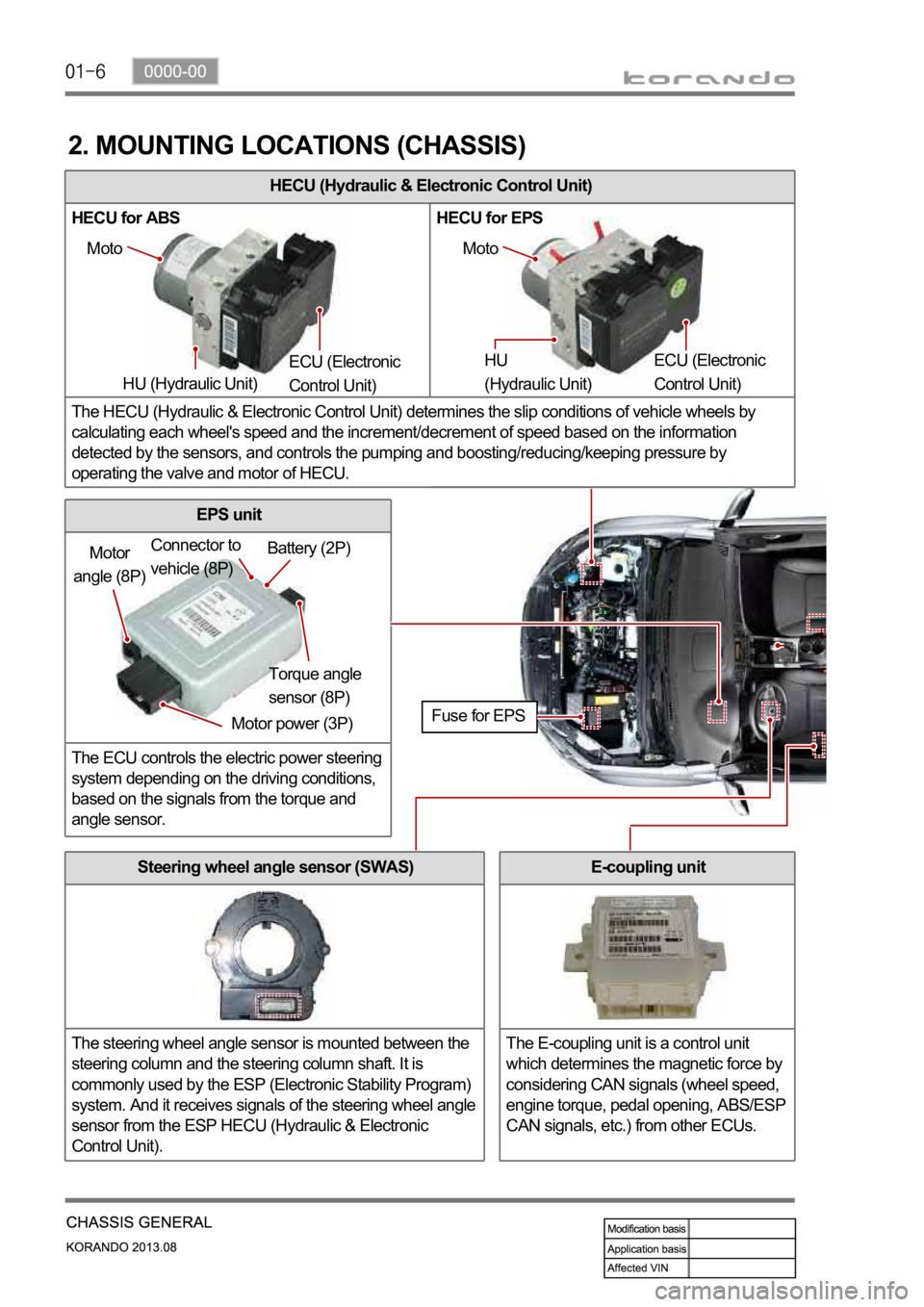
HECU (Hydraulic & Electronic Control Unit)
HECU for ABS HECU for EPS
The HECU (Hydraulic & Electronic Control Unit) determines the slip conditions of vehicle wheels by
calculating each wheel's speed and the increment/decrement of speed based on the information
detected by the sensors, and controls the pumping and boosting/reducing/keeping pressure by
operating the valve and motor of HECU.
2. MOUNTING LOCATIONS (CHASSIS)
Moto
HU (Hydraulic Unit) ECU (Electronic
Control Unit) Moto
HU
(Hydraulic Unit) ECU (Electronic
Control Unit)
Motor
angle (8P)
Motor power (3P)Torque angle
sensor (8P) Battery (2P) Connector to
vehicle (8P)
Fuse for EPS
Steering wheel angle sensor (SWAS)
The steering wheel angle sensor is mounted between the
steering column and the steering column shaft. It is
commonly used by the ESP (Electronic Stability Program)
system. And it receives signals of the steering wheel angle
sensor from the ESP HECU (Hydraulic & Electronic
Control Unit).
EPS unit
The ECU controls the electric power steering
system depending on the driving conditions,
based on the signals from the torque and
angle sensor.
E-coupling unit
The E-coupling unit is a control unit
which determines the magnetic force by
considering CAN signals (wheel speed,
engine torque, pedal opening, ABS/ESP
CAN signals, etc.) from other ECUs.
Page 986 of 1336
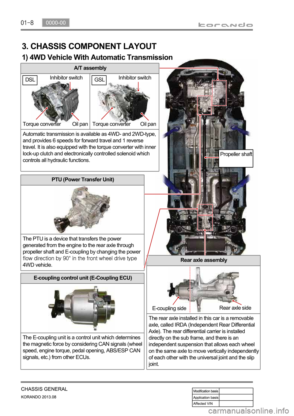
A/T assembly
Automatic transmission is available as 4WD- and 2WD-type,
and provides 6 speeds for forward travel and 1 reverse
travel. It is also equipped with the torque converter with inner
lock-up clutch and electronically controlled solenoid which
controls all hydraulic functions.
3. CHASSIS COMPONENT LAYOUT
PTU (Power Transfer Unit)
The PTU is a device that transfers the power
generated from the engine to the rear axle through
propeller shaft and E-coupling by changing the power
4WD vehicle.Rear axle assembly
The rear axle installed in this car is a removable
axle, called IRDA (Independent Rear Differential
Axle). The rear differential carrier is installed
directly on the sub frame, and there is an
independent suspension that allows each wheel
on the same axle to move vertically independentl
y
of each other with the universal joint and the slip
joint.
E-coupling control unit (E-Coupling ECU)
The E-coupling unit is a control unit which determines
the magnetic force by considering CAN signals (wheel
speed, engine torque, pedal opening, ABS/ESP CAN
signals, etc.) from other ECUs.
Inhibitor switch
Torque converter Oil pan
E-coupling sideRear axle side
Propeller shaft
1) 4WD Vehicle With Automatic Transmission
GSLDSLInhibitor switch
Torque converter Oil pan
Page 987 of 1336
0000-00
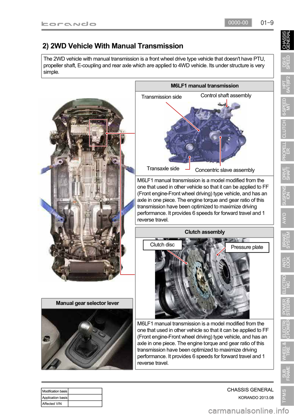
M6LF1 manual transmission
M6LF1 manual transmission is a model modified from the
one that used in other vehicle so that it can be applied to FF
(Front engine-Front wheel driving) type vehicle, and has an
axle in one piece. The engine torque and gear ratio of this
transmission have been optimized to maximize driving
performance. It provides 6 speeds for forward travel and 1
reverse travel.
Clutch assembly
M6LF1 manual transmission is a model modified from the
one that used in other vehicle so that it can be applied to FF
(Front engine-Front wheel driving) type vehicle, and has an
axle in one piece. The engine torque and gear ratio of this
transmission have been optimized to maximize driving
performance. It provides 6 speeds for forward travel and 1
reverse travel.
The 2WD vehicle with manual transmission is a front wheel drive type vehicle that doesn't have PTU,
propeller shaft, E-coupling and rear axle which are applied to 4WD vehicle. Its under structure is very
simple.
Manual gear selector lever
Transmission sideControl shaft assembly
Transaxle side
Concentric slave assembly
Pressure plate
2) 2WD Vehicle With Manual Transmission
Clutch disc
Page 997 of 1336
0000-00
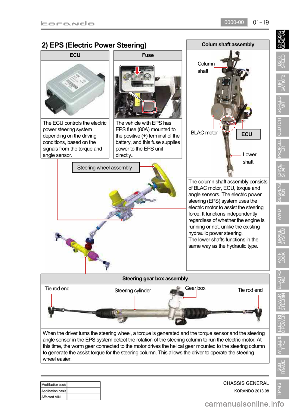
ECU
The ECU controls the electric
power steering system
depending on the driving
conditions, based on the
signals from the torque and
angle sensor.
2) EPS (Electric Power Steering)
Fuse
The vehicle with EPS has
EPS fuse (80A) mounted to
the positive (+) terminal of the
battery, and this fuse supplies
power to the EPS unit
directly..
Steering gear box assembly
When the driver turns the steering wheel, a torque is generated and the torque sensor and the steering
angle sensor in the EPS system detect the rotation of the steering column to run the electric motor. At
this time, the worm gear connected to the motor drives the helical gear mounted to the steering column
to generate the assist torque for the steering column. This allows the driver to operate the steering
wheel easier.
ECU
Tie rod end
Tie rod end Gear boxSteering cylinder
Steering wheel assembly
BLAC motor
Lower
shaft Column
shaft
Colum shaft assembly
The column shaft assembly consists
of BLAC motor, ECU, torque and
angle sensors. The electric power
steering (EPS) system uses the
electric motor to assist the steering
force. It functions independently
regardless of whether the engine is
running or not, unlike the existing
hydraulic power steering.
The lower shafts functions in the
same way as the hydraulic type.
Page 999 of 1336

0000-00
3) General Instructions
Before lifting up the vehicle with a lift, correctly support the lifting points.
When using a jack, park the vehicle on a level ground and place the wheel chocks under the tires.
Position the jack under the frame and lift up the vehicle and then support with chassis stand before
service work.
Make sure to disconnect the negative (-) cable from the battery to prevent any damage to electric
systems.
If you have to work on vehicle, cover the seats and floor with protection covers to avoid any
damage and contamination.
Brake fluid and anti-freeze can damage the painted surface of body. So carefully handle them
during service work.
To improve the efficiency of service work, use only recommended and specified tools.
Use only Ssangyong genuine spare parts.
Never reuse the cotter pin, gasket, O-ring, oil seal, lock washer and self-locking nut. Replace them
with new ones. If reused, normal functions cannot be maintained.
Store the disassembled parts as a set based on disassembly order and unit.
Pay particular attention not to miss or mix the fasteners.
If necessary, especially for inspection, clean the removed parts completely.
Apply the oil or grease on the running and sliding surfeces before installation. Use the specified
sealant and gasket to prevent leakage if necessary.
Tighten the fasteners to the specified tightening torque.
As a final stage of service work, check if the serviced system is working properly and the problem
has been eliminated clearly. (1)
(2)
(3)
(4)
(5)
(6)
(7)
(8)
(9)
(10)
(11)
(12)
(13)
(14) Remove the engine and transaxle as a set.
Manual transaxle: Transaxle can be separated after removing the front module (sub frame, engine
and transaxle).
Automatic transaxle: Transaxle can be separated after removing the sub frame. -
-
2) Equipment
Korando is FF (Front Engine Front Drive) type vehicle, and engine and powertrain system are
integrated into a module. Therefore, 2-post lift and general equipment are necessary when working
on the engine and transmission.
Major equipment: Engine and transmission jack, Engine stand, Engine crane, Transmission jack,
Engine hanger -
-
Engine stand
Engine crane
Page 1000 of 1336

4) Basic Inspection
(1) Horn operation
Listen for the horn sound when pressing the horn pad on the steering wheel. -
(2) Brake operation
Check if there is any abnormal noise, unusually long braking distance, or uneven braking force. If the
brake warning lamp does not go out even after starting the engien or are flashing during driving,
have the brake system checked immediately.
Check the brake pipes and hoses for connection, oil leak, crack or interference after changing the
position of tires. When replacing the tires, check the brake disc for surface condition and wear.
Check the parking brake cable and brake operation. Shorten the checking interval if the parking
brake is used frequently. -
-
-
(3) Exhaust system
Be aware to any changes in sound or smell from the exhaust system. These may be caused by leak or
overheat. Have the exhaust system checked and repaired immediately.
Inspect the exhaust system including catalytic converter. Inspect all the components and body frame
near the exhaust system. -
-
(4) Tires
Unusual vibration of the steering wheel and seats or pulling to one side on the straight and level roads
may indicates the uneven tire inflation pressure or poor wheel balance. -
(5) Steering and suspension system
Inspect the front and rear suspension and the steering system for damage, looseness or missing
parts, signs of wear or lack of lubrication. Inspect the power steering line and the hoses for
connection, leak, crack and chafing. Inspect the drive axle boot and seals for damage, tear or leak.
Replace or repair the system if necessary. -
(6) Engine oil
Check the oil level when the engine is still warm and add the specified engine oil if necessary. -
(7) Coolant
Check the coolant level in the coolant reservoir, coolant conditions (contamination, foreign material),
and hoses for damage and leak. Replace or add the Ssangyong genuine coolant, if needed. -
(8) Engine drive belt
Check all drive belts on the engine for wear, crack and looseness. Retighten or replace the belt, if
needed. -
Page 1004 of 1336
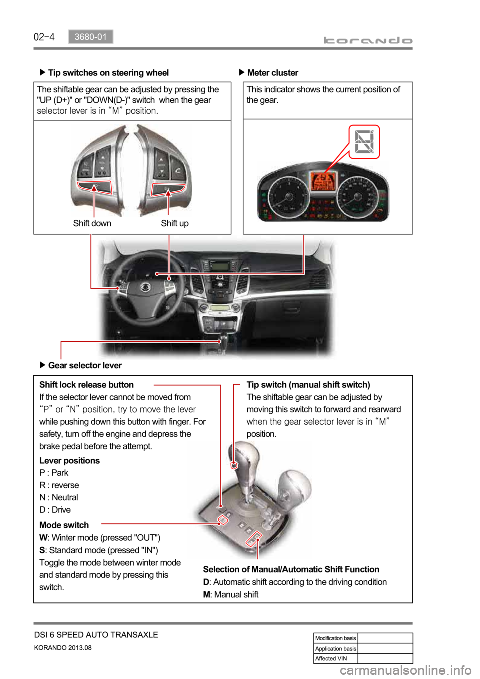
The shiftable gear can be adjusted by pressing the
"UP (D+)" or "DOWN(D-)" switch when the gear
Shift lock release button
If the selector lever cannot be moved from
while pushing down this button with finger. For
safety, turn off the engine and depress the
brake pedal before the attempt.Shift up Shift down Tip switches on steering wheel
Meter cluster
This indicator shows the current position of
the gear.
Gear selector lever
Lever positions
P : Park
R : reverse
N : Neutral
D : Drive
Mode switch
W: Winter mode (pressed "OUT")
S: Standard mode (pressed "IN")
Toggle the mode between winter mode
and standard mode by pressing this
switch.Tip switch (manual shift switch)
The shiftable gear can be adjusted by
moving this switch to forward and rearward
position.
Selection of Manual/Automatic Shift Function
D: Automatic shift according to the driving condition
M: Manual shift