Page 514 of 1336

Problem Possible Cause Action
Coolant
level is too low
Coolant
temperature is
too high
2. INSPECTION
Leak from the radiator
Leak from the coolant auxiliary tank
Leak from the heater core -
-
-
Leak from the water inlet cap
Leak from the thermostat housing -
-Reconnect the hose or replace the
clamp
Change the hose -
- Leak from the coolant hose connections
Damaged coolant hose -
-
Change the gasket
Change the water pump -
- Leak from the water pump gasket
Leak from the water pump internal seal -
-
Tighten the bolts to the specified
torque
Change the cylinder head gasket -
- Incorrect tightening torque of the cylinder
head bolts
Damaged cylinder head gasket -
-Change the water inlet cap gasket
Change the thermostat sealing -
-
Coolant leakage (Coolant level is low)
Improper coolant mixture ratio
Kinked coolant hose -
-
-Add coolant
Check the coolant concentration
(Anti-freeze)
Repair or replace the hose -
-
-
Defective thermostat
Defective water pump
Defective radiator
Defective coolant auxiliary tank or tank
cap -
-
-
-Change the thermostat
Change the water pump
Change the radiator
Change the coolant auxiliary tank or
tank cap -
-
-
-Change the radiator
Change the coolant auxiliary tank
Change the heater -
-
-
Cracks on the cylinder block or
cylinder head
Clogged coolant passages in the
cylinder block or cylinder head -
-Change cylinder block or cylinder
head
Clean the coolant passage -
-
Clogged radiator core -
Replace the sensor or repair the
related wiring - Improper operation of cooling fan -Clean the radiator core -
Defective temperature sensor or faulty
wiring -Replace the cooling fan or repair the
related circuit -
Page 599 of 1336
0000-00
3. BASIC INSPECTION
1) Battery Terminal
Make sure the terminal connections are
securely tightened. If the terminals are
corroded, clean them or replace the battery. -
* Cleaning
Remove the corrosion or dirt with a wire brush
or sand paper, and then wash out with
lukewarm soapy water.
2) Measuring the Voltage Drop
Measuring at battery terminal
Measure the voltage between battery
terminal (+. -) and wiring clamp. -
Specified valuebelow 0.3V
If the terminals are corroded, clean and
retightening them. If the specified tightening
torque cannot be kept, replace the clamp.
Terminal (+)
Terminal (-)
Terminal (+): 4 ~ 5 Nm
Page 999 of 1336

0000-00
3) General Instructions
Before lifting up the vehicle with a lift, correctly support the lifting points.
When using a jack, park the vehicle on a level ground and place the wheel chocks under the tires.
Position the jack under the frame and lift up the vehicle and then support with chassis stand before
service work.
Make sure to disconnect the negative (-) cable from the battery to prevent any damage to electric
systems.
If you have to work on vehicle, cover the seats and floor with protection covers to avoid any
damage and contamination.
Brake fluid and anti-freeze can damage the painted surface of body. So carefully handle them
during service work.
To improve the efficiency of service work, use only recommended and specified tools.
Use only Ssangyong genuine spare parts.
Never reuse the cotter pin, gasket, O-ring, oil seal, lock washer and self-locking nut. Replace them
with new ones. If reused, normal functions cannot be maintained.
Store the disassembled parts as a set based on disassembly order and unit.
Pay particular attention not to miss or mix the fasteners.
If necessary, especially for inspection, clean the removed parts completely.
Apply the oil or grease on the running and sliding surfeces before installation. Use the specified
sealant and gasket to prevent leakage if necessary.
Tighten the fasteners to the specified tightening torque.
As a final stage of service work, check if the serviced system is working properly and the problem
has been eliminated clearly. (1)
(2)
(3)
(4)
(5)
(6)
(7)
(8)
(9)
(10)
(11)
(12)
(13)
(14) Remove the engine and transaxle as a set.
Manual transaxle: Transaxle can be separated after removing the front module (sub frame, engine
and transaxle).
Automatic transaxle: Transaxle can be separated after removing the sub frame. -
-
2) Equipment
Korando is FF (Front Engine Front Drive) type vehicle, and engine and powertrain system are
integrated into a module. Therefore, 2-post lift and general equipment are necessary when working
on the engine and transmission.
Major equipment: Engine and transmission jack, Engine stand, Engine crane, Transmission jack,
Engine hanger -
-
Engine stand
Engine crane
Page 1002 of 1336
3. STANDARD BOLTS SPECIFICATIONS
Metric bolt strength is embossed on the head of each bolt. The strength of bolt can be classified as
4T, 7T, 8.8T, 10.9T, 11T and 12.9T in general.
Observe standard tightening torque during bolt tightening works and can adjust torque to be proper
within 15 % if necessary. Try not to over max. allowable tightening torque if not required to do so.
Determine extra proper tightening torque if tightens with washer or packing.
If tightens bolts on the below materials, be sure to determine the proper torque. 1)
2)
3)
4)
Aluminum alloy: Tighten to 80 % of above torque table.
Plastics: Tighten to 20 % of above torque table. -
-
Page 1007 of 1336

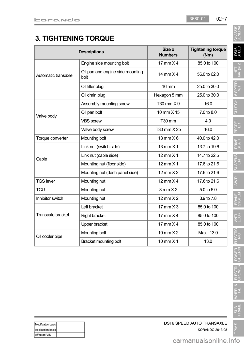
3680-01
3. TIGHTENING TORQUE
DescriptionsSize x
NumbersTightening torque
(Nm)
Automatic transaxleEngine side mounting bolt 17 mm X 4 85.0 to 100
Oil pan and engine side mounting
bolt14 mm X 4 56.0 to 62.0
Oil filler plug 16 mm 25.0 to 30.0
Oil drain plug Hexagon 5 mm 25.0 to 30.0
Valve bodyAssembly mounting screw T30 mm X 9 16.0
Oil pan bolt 10 mm X 15 7.0 to 8.0
VBS screw T30 mm 4.0
Valve body screw T30 mm X 25 16.0
Torque converter Mounting bolt 13 mm X 6 40.0 to 42.0
CableLink nut (switch side) 13 mm X 1 13.7 to 19.6
Link nut (cable side) 12 mm X 1 14.7 to 22.5
Mounting nut (floor side) 12 mm X 1 17.6 to 21.6
Mounting nut (dash panel side) 12 mm X 2 17.6 to 21.6
TGS lever Mounting nut 12 mm X 4 17.6 to 21.6
TCU Mounting nut 8 mm X 2 5.0 to 6.0
Inhibitor switch Mounting nut 12 mm X 2 3.9 to 7.8
Transaxle bracketLeft bracket 17 mm X 3 85.0 to 100
Right bracket 17 mm X 4 85.0 to 100
Upper bracket 17 mm X 4 85.0 to 100
Oil cooler pipeMounting bolt 10 mm X 2 Max.: 13.0
Bracket mounting bolt 10 mm X 1 13.0
Page 1034 of 1336

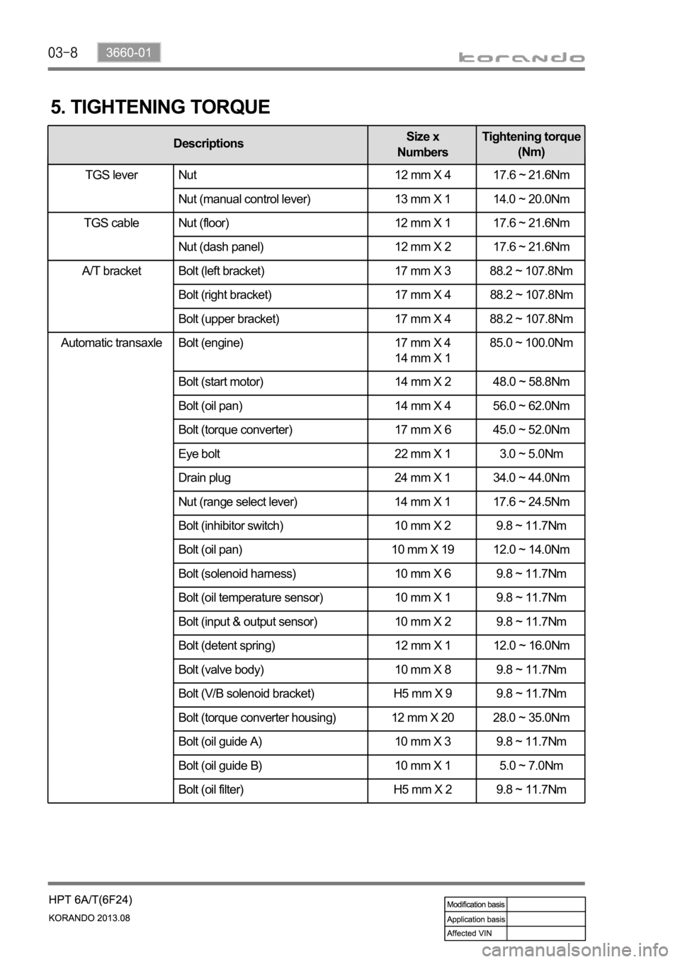
Automatic transaxle Bolt (engine) 17 mm X 4
14 mm X 1 85.0 ~ 100.0Nm
Bolt (start motor) 14 mm X 2 48.0 ~ 58.8Nm
Bolt (oil pan) 14 mm X 4 56.0 ~ 62.0Nm
Bolt (torque converter) 17 mm X 6 45.0 ~ 52.0Nm
Eye bolt 22 mm X 1 3.0 ~ 5.0Nm
Drain plug 24 mm X 1 34.0 ~ 44.0Nm
Nut (range select lever) 14 mm X 1 17.6 ~ 24.5Nm
Bolt (inhibitor switch) 10 mm X 2 9.8 ~ 11.7Nm
Bolt (oil pan) 10 mm X 19 12.0 ~ 14.0Nm
Bolt (solenoid harness) 10 mm X 6 9.8 ~ 11.7Nm
Bolt (oil temperature sensor) 10 mm X 1 9.8 ~ 11.7Nm
Bolt (input & output sensor) 10 mm X 2 9.8 ~ 11.7Nm
Bolt (detent spring) 12 mm X 1 12.0 ~ 16.0Nm
Bolt (valve body) 10 mm X 8 9.8 ~ 11.7Nm
Bolt (V/B solenoid bracket) H5 mm X 9 9.8 ~ 11.7Nm
Bolt (torque converter housing) 12 mm X 20 28.0 ~ 35.0Nm
Bolt (oil guide A) 10 mm X 3 9.8 ~ 11.7Nm
Bolt (oil guide B) 10 mm X 1 5.0 ~ 7.0Nm
Bolt (oil filter) H5 mm X 2 9.8 ~ 11.7Nm
5. TIGHTENING TORQUE
DescriptionsSize x
NumbersTightening torque
(Nm)
TGS lever Nut 12 mm X 4 17.6 ~ 21.6Nm
Nut (manual control lever) 13 mm X 1 14.0 ~ 20.0Nm
Nut (floor) 12 mm X 1 17.6 ~ 21.6Nm
Nut (dash panel) 12 mm X 2 17.6 ~ 21.6Nm
A/T bracket Bolt (left bracket) 17 mm X 3 88.2 ~ 107.8Nm
Bolt (right bracket) 17 mm X 4 88.2 ~ 107.8Nm
Bolt (upper bracket) 17 mm X 4 88.2 ~ 107.8Nm
TGS lever
TGS cable
Page 1035 of 1336
3660-01
DescriptionsSize x
NumbersTightening torque
(Nm)
Automatic
transaxleBolt (oil lubrication pipe) 10 mm X 1 9.8 ~ 11.7Nm
Bolt (oil pump) 12 mm X 7 20.0 ~ 26.0Nm
Bolt (parking rod guide) 10 mm X 2 9.8 ~ 11.7Nm
Bolt (U/D brake retainer) T40 X 6 31.0 ~ 36.0Nm
Bolt (U/D brake chamber) T30 X 2 4.9 ~ 9.8Nm
Bolt (rear cover) 12 mm X 13 28.0 ~ 35.0Nm
Page 1056 of 1336
3190-01
2. TIGHTENING TORQUE
Part name Tightening torque Remark
1. Drive gear mounting bolt of differential carrier 166.6 to 176.4 Nm 10 EA
2. Reverse shaft mounting bolt 74.5 to 89.2 Nm
3. Transmission case mounting bolt 19.6 to 26.5 Nm 22 EA
4. Concentric slave cylinder mounting bolt 11.8 to 14.7 Nm 3 EA
5. Backup lamp switch 29.4 to 34.3 Nm
6. Neutral switch 29.4 to 34.3 Nm
7. Oil filler plug 58.8 to 78.4 Nm
8. Oil drain plug 58.8 to 78.4 Nm
9. Oil plug 58.8 to 78.4 Nm
10. Shift lever mounting nut 42.2 to 53.9 Nm
11. Selector lever mounting nut 42.2 to 53.9 Nm
12. Control shaft assembly mounting bolt 9.8 to 11.8 Nm 7 EA
13. Guide bolt 42.2 to 53.9 Nm