Page 608 of 1336
2) Voltage Check (with load)
1Push the load switch to ON (to arrow
direction) direction for less than 5 seconds. 1.
Read the measurement. 2.
Specified
value7 ~ 9V (Red): Over discharged
or faulty
9 ~ 11V (Yellow): Charging
required
11 ~ 13V: Normal
To identify the battery capacity with the
voltage drop (V) value, discharge the fixed
load capacity (120A) for a certain period (5
seconds).
Page 629 of 1336
8410-00
1. CAUTIONS WHEN WORKING ON ELECTRICAL UNITS
Disconnect the negative cable from the battery
in advance when working on electrical units. -
If a fuse is blown, replace it with a fuse which
has the correct amperage rating. If you use a
fuse with higher capacity than the
specification, the component can be
damaged or catch fire. -Do not drop or appy excessive impact to
sensors and relays. -
10 A 15 A
Make sure to turn "OFF" the ignition switch
and other lamp switches before disconnecting
or connecting the negative battery cable.
(Otherwise, semiconductor parts can be
damaged.)
Page 1221 of 1336

6810-00
5. PTC HEATER OPERATION PROCESS
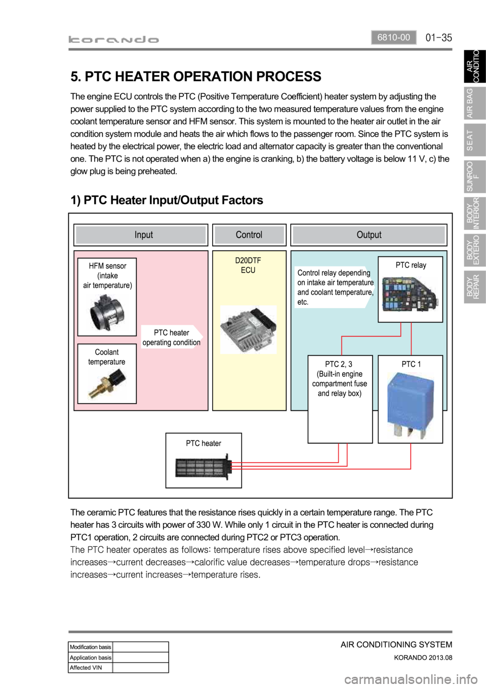
1) PTC Heater Input/Output Factors
The engine ECU controls the PTC (Positive Temperature Coefficient) heater system by adjusting the
power supplied to the PTC system according to the two measured temperature values from the engine
coolant temperature sensor and HFM sensor. This system is mounted to the heater air outlet in the air
condition system module and heats the air which flows to the passenger room. Since the PTC system is
heated by the electrical power, the electric load and alternator capacity is greater than the conventional
one. The PTC is not operated when a) the engine is cranking, b) the battery voltage is below 11 V, c) the
glow plug is being preheated.
The ceramic PTC features that the resistance rises quickly in a certain temperature range. The PTC
heater has 3 circuits with power of 330 W. While only 1 circuit in the PTC heater is connected during
PTC1 operation, 2 circuits are connected during PTC2 or PTC3 operation.