2013 SMART FORTWO COUPE ELECTRIC DRIVE transmission
[x] Cancel search: transmissionPage 81 of 218
!
When the hill‑start assist system stops
braking the vehicle, it can roll
backwards.
If you open the driver’s door, the
hill‑start assist system is deactivated
and a warning signal sounds.
Your vehicle has a hill‑start assist system.
On uphill grades the hill‑start assist
system maintains the pressure in the brake
system for approximately one second after
you have released the brake pedal.
Therefore, you can start off smoothly
without the vehicle moving immediately
after releasing the brake pedal.
X Release the brake pedal.
X Apply sufficient pressure to the
accelerator pedal to drive off.
On uphill grades with higher inclination,
the hill-start assist system will release
the pressure in the brake system after
approximately two seconds. A warning
signal sounds and the transmission
position indicator shows a flashing N in
order to warn you of the vehicle rolling
backwards.
X Press the brake pedal.
X Release the brake pedal.
X Apply sufficient pressure to the
accelerator pedal to drive off.
i The hill‑start assist system is inactive
if you start off with the parking brake
engaged. Instrument cluster
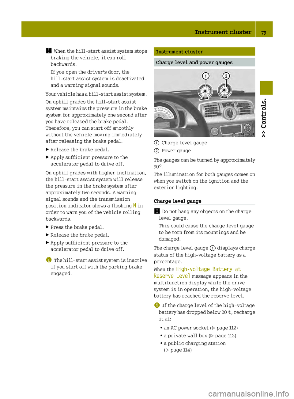
Charge level and power gauges
0002
Charge level gauge
0003 Power gauge
The gauges can be turned by approximately
90°.
The illumination for both gauges comes on
when you switch on the ignition and the
exterior lighting.
Charge level gauge !
Do not hang any objects on the charge
level gauge.
This could cause the charge level gauge
to be torn from its mountings and be
damaged.
The charge level gauge 0002displays charge
status of the high-voltage battery as a
percentage.
When the High-voltage Battery at Reserve Level message appears in the
multifunction display while the drive
system is in operation, the high-voltage
battery has reached the reserve level.
i If the charge level of the high-voltage
battery has dropped below 20 %, recharge
it at:
R an AC power socket (Y page 112)
R a private wall box (Y page 112)
R a public charging station
(Y page 114) Instrument cluster
79>> Controls. Z
Page 83 of 218
Control system
Introduction
The control system is activated when you
turn the key in the starter switch to
position 1. G
WARNING
Ad river’s attention to the road and traffic
conditions must always be his/her primary
focus when driving.
In order to avoid distraction which could
lead to an accident, the driver should
select features and change settings in the
control system only vehicle at a standstill
or when traffic and road conditions permit
it to be done safely.
Bear in mind that at a speed of just 30 mph
(approximately 50 km/h ), your vehicle is
covering adistance of 44 feet
(approximately 14 m) every second. Control lever
You can select the displays in the
multifunction display and change settings
in the control system with the control
lever. 0002
Control switch
Pressing up selects a menu.
0003
OK button
Confirming a selection.
Scrolling through stored messages
in the
Messages menu
002B
Control switch
Pressing down selects a menu.
Multifunction display
The multifunction display shows values and
settings as well as display messages.
X Activating the multifunction display:
Unlock the vehicle.
X Confirming messages: Press the OK
button on the control lever briefly
(Y page 81).
X Exiting menu: Press the control switch on
the control lever up or down until the
message Back appears in the
multifunction display.
X Press the OK button on the control lever
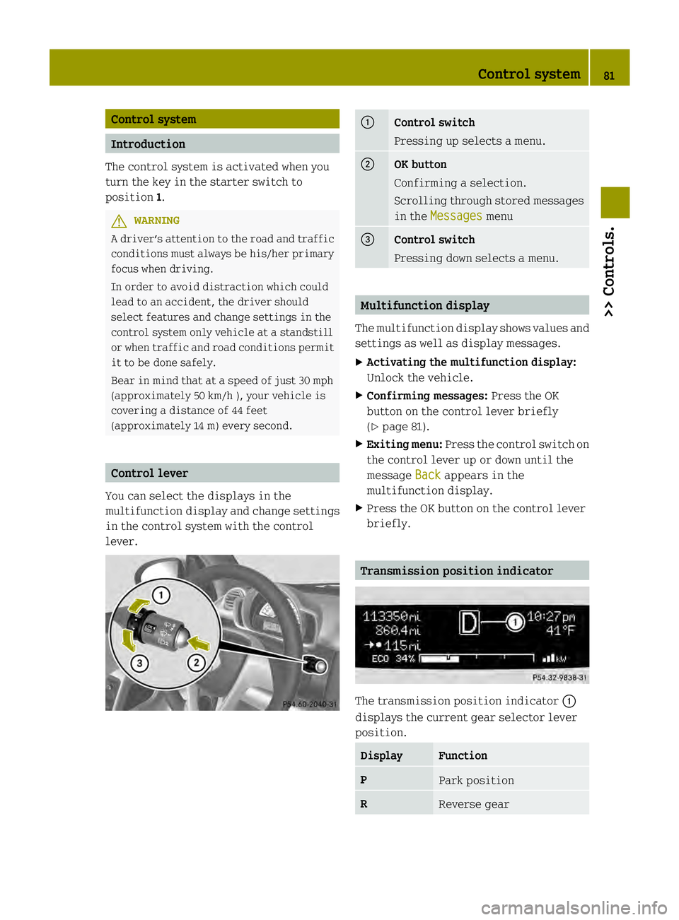
briefly. Transmission position indicator
The transmission position indicator
0002
displays the current gear selector lever
position. Display Function
P
Park position
R
Reverse gear Control system
81>> Controls. Z
Page 114 of 218
Carry out the following steps within
30 seconds:
X If the value of the charg ecurrent is not
set to 8 A: set the value to 8 Aand confirm.
X Set the value of the charge current to
10 A and confirm.
X Set the value of the charge current to
8 A and confirm.
X Set the value of the charge current to
10 A and confirm.
X Press the encryption button on the
powerline adapter withi nthree minutes.
When the powerline adapter shows a
connection, the connection process was
successful.
i Observe the separate operating
instructions of the powerline adapter.
i Contact an authorized electric drive
smart center if you have any questions.
X Next, set the value of the charge current
to the desired value once again.
As soon as the vehicle establishes an
Internet connection, you can also use the
"Vehicle Homepage" at home during the
charging process. Changes you have made
via the "Vehicle Homepage" are adopted
after the charging process is complete.
This data transmission ends after
approximately three days. Charging at an AC power socket or a
private wallbox
Charging cable G
WARNING
The drive system is under high voltage.
Only use the charging cable that is
supplied with the vehicle or a wallbox
charging cable . Only use these charging
cables to charge the vehicle. Do not extend
a charging cable. Do not use a charging
cable if it is damaged. You could otherwise suffer an electric
shock and be seriously or even fatally
injured.
When charging at a private wallbox or
public charging station (level 2charging),
the charging cable is non-detachably
connected to the wallbox or charging
station.
Storing the charging cable You can store the charging cable in the
vehicle.
R
cabrio:
-in a box which is available as a
separate accessory (part number A 451
810 00 80).
- in the storage compartment in the
tailgate, if available (Y page 104).
In this case, you can not stow the roof
bars of the roof system there.
R coupé: in the storage compartment in the
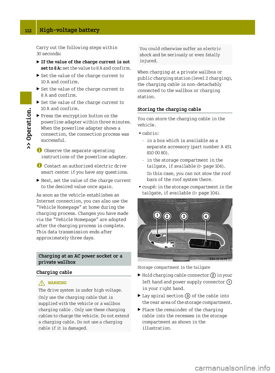
tailgate, if available (Y page 104). Storage compartment in the tailgate
X
Hold charging cable connector 0003in your
left hand and power supply connector 0002
in your right hand.
X Lay spiral section 002Bof the cable into
the rear area of the storage compartment.
X Place the remainder of the charging
cable into the recesses in the storage
compartment as shown in the
illustration. 112
High-voltage battery>> Operation.
Page 128 of 218
responsibility to maintain correct tire
pressure, even if underinflation has not
reached the level to trigger illumination
of the TPMS low tire pressure telltale.
Your vehicle has also been equipped with a
TPMS malfunction indicator to indicate
when the system is not operating properly.
The TPMS malfunction indicator is
combined with the low tire pressure
telltale. When the system detects a
malfunction, the telltale will flash for
approximately 1 minute and then remain
continuously illuminated.
This sequence will continue upon
subsequent vehicle start-ups as long as the
malfunction exists. When the malfunction
indicator is illuminated, the system may
not be able to detect or signal low tire
pressure as intended.
TPMS malfunctions may occur for a variety
of reasons, including the installation of
incompatible replacement or alternate
tires or wheels on the vehicle that prevent
the TPMS from functioning properly. Always
check the TPMS malfunction telltale after
replacing one or more tires or wheels on
your vehicle to ensure that the replacement
or alternate tires and wheels allow the
TPMS to continue to function properly.
i If a condition causing the TPMS to
malfunction develops, it may take up to
10 minutes for the system to signal a
malfunction using the TPMS telltale
flashing and illumination sequence.
The telltale extinguishes after a few
minutes driving if the malfunction has
been corrected.
i Operating radio transmission
equipment (e.g. wireless headsets, two-
way radios) in or near the vehicle could
cause the TPMS to malfunction. i
USA only:
This device complies with Part 15 of the
FCC Rules. Operation is subject to the
following two conditions:
R This device may not cause harmful
interference, and
R this device must accept any
interference received, including
interference that may cause undesired
operation.
Any unauthorized modification to this
device could void the user’s authority to
operate the equipment.
i Canada only:
This device complies with RSS‑210 of
Industry Canada. Operation is subject to
the following two conditions:
R This device may not cause
interference, and
R this device must accept any
interference received, including
interference that may cause undesired
operation of the device.
Any unauthorized modification to this
device could void the user’s authority to
operate the equipment.
Restarting the TPMS G
WARNING
It is the driver’s responsibility to
calibrate the TPMS on the recommended
cold inflation pressure. Underinflated
tires affect the ability to steer or brake
and might cause you to lose control of the
vehicle.
When you restart the TPMS, the system sets
new reference values for each tire.
The TPMS must be restarted when you have
adjusted the tire inflation pressure to a
new level (e.g. because of differen tload or
driving conditions). The TPMS is then
recalibrated to the current tire inflation
pressures. 126
Tires and wheels>> Operation.
Page 139 of 218
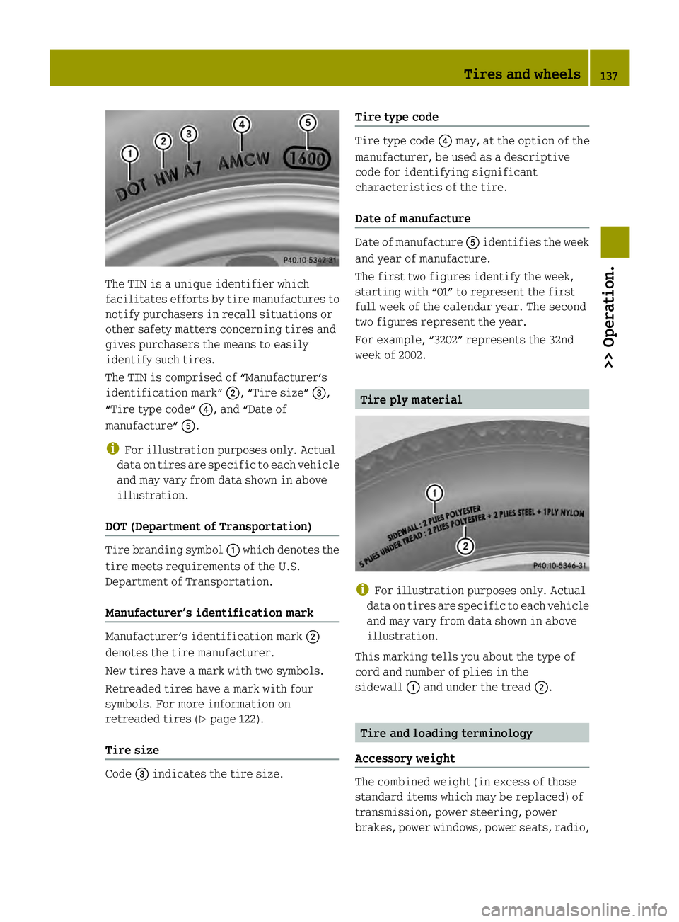
The TIN is a unique identifier which
facilitates efforts by tire manufactures to
notify purchasers in recall situations or
other safety matters concerning tires and
gives purchasers the means to easily
identify such tires.
The TIN is comprised of “Manufacturer’s
identification mark” 0003, “Tire size”002B,
“Tire type code” 002A, and “Date of
manufacture” 0028.
i For illustration purposes only. Actual
data on tires are specific to each vehicle
and may vary from data shown in above
illustration.
DOT (Department of Transportation) Tire branding symbol
0002which denotes the
tire meets requirements of the U.S.
Department of Transportation.
Manufacturer’s identification mark Manufacturer’s identification mark
0003
denotes the tire manufacturer.
New tires have a mark with two symbols.
Retreaded tires have a mark with four
symbols. For more information on
retreaded tires (Y page 122).
Tire size Code
002Bindicates the tire size. Tire type code Tire type code
002Amay, at the option of the
manufacturer, be used as a descriptive
code for identifying significant
characteristics of the tire.
Date of manufacture Date of manufacture
0028identifies the week
and year of manufacture.
The first two figures identify the week,
starting with “01” to represent the first
full week of the calendar year. The second
two figures represent the year.
For example, “3202” represents the 32nd
week of 2002. Tire ply material
i
For illustration purposes only. Actual
data on tires are specific to each vehicle
and may vary from data shown in above
illustration.
This marking tells you about the type of
cord and number of plies in the
sidewall 0002and under the tread 0003. Tire and loading terminology
Accessory weight The combined weight (in excess of those
standard items which may be replaced) of
transmission, power steering, power
brakes, power windows, power seats, radio, Tires and wheels
137>> Operation. Z
Page 157 of 218
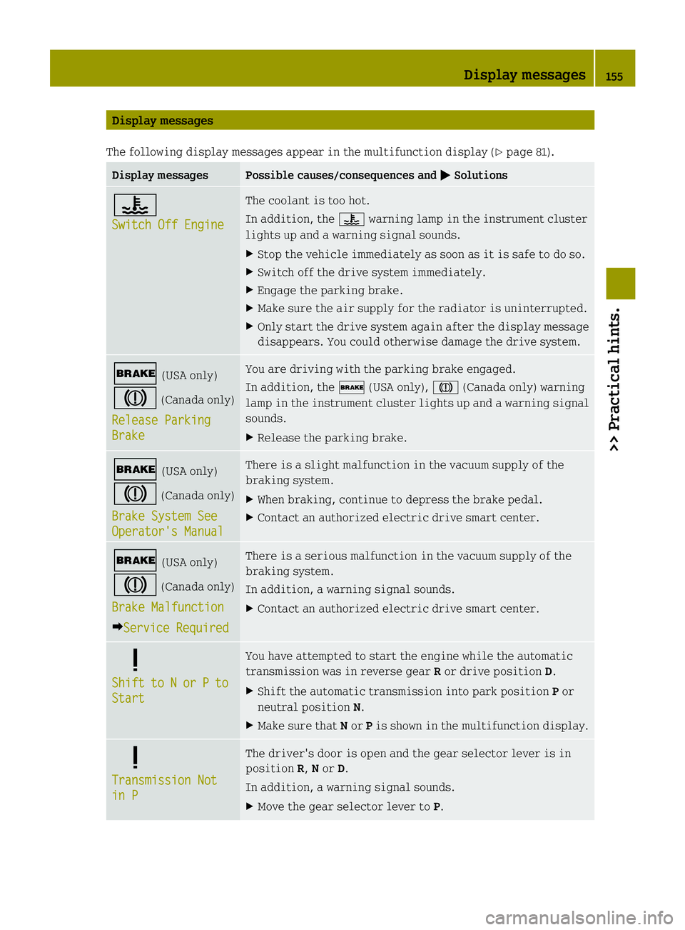
Display messages
The following display messages appear in the multifunction displa y(Ypage 81). Display messages Possible causes/consequences and
0001 Solutions
0005
Switch Off Engine The coolant is too hot.
In addition, the
0005warning lamp in the instrument cluster
lights up and a warning signal sounds.
X Stop the vehicle immediately as soon as it is safe to do so.
X Switch off the drive system immediately.
X Engage the parking brake.
X Make sure the air supply for the radiator is uninterrupted.
X Only start the drive system again after the display message
disappears. You could otherwise damage the drive system. 0002
(USA only)
0001 (Canada only)
Release Parking Brake You are driving with the parking brake engaged.
In addition, the 0002(USA only), 0001(Canada only) warning
lamp in the instrument cluster lights up and a warning signal
sounds.
X Release the parking brake. 0002
(USA only)
0001 (Canada only)
Brake System See Operator's Manual There is a slight malfunction in the vacuum supply of the
braking system.
X
When braking, continue to depress the brake pedal.
X Contact an authorized electric drive smart center. 0002
(USA only)
0001 (Canada only)
Brake Malfunction 0001Service Required There is a serious malfunction in the vacuum supply of the
braking system.
In addition, a warning signal sounds.
X
Contact an authorized electric drive smart center. 0001
Shift
to N or P to
Start You have attempted to start the engine while the automatic
transmission was in reverse gear
Ror drive position D.
X Shift the automatic transmission into park position Por
neutral position N.
X Make sure that Nor Pis shown in the multifunction display. 0001
Transmission Not
in P The driver's door is open and the gear selector lever is in
position
R,Nor D.
In addition, a warning signal sounds.
X Move the gear selector lever to P. Display messages
155>> Practical hints. Z
Page 194 of 218
Disconnecting, removing, charging,
reinstalling and reconnecting 12‑volt
battery
Disconnecting the 12-volt battery i
If the 12-volt battery is disconnected
or discharged
R turning the key in the starter switch
will have no effect
R the transmission will remain in park
position P
For more information see “Jump
starting” (Y page 193).
X Engage the parking brake.
X Move the gear selector lever to park
position P.
X Turn off all electrical accessories.
X Switch off the drive system.
X Open the passenger door.
X Move the passenger seat to the rear as far
as possible.
X Unscrew the carpet holder in the
passenger footwell (Y page 154).
X Lift the carpet. X
Unscrew fastening screw 0003
counterclockwise.
X Pull footrest 0002sideways out of the
vehicle.
X Read and observ esafety instructions and
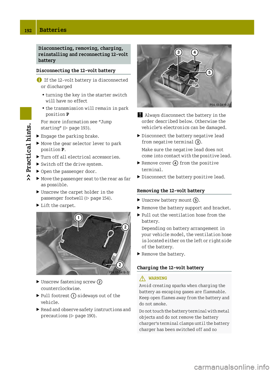
precautions (Y page 190). !
Always disconnect the battery in the
order described below. Otherwise the
vehicle’s electronic scan be damaged.
X Disconnect the battery negative lead
from negative terminal 002B.
Make sure the negative lead does not
come into contact with the positive lead.
X Remove cover 002Afrom the positive
terminal.
X Disconnect the battery positive lead.
Removing the 12-volt battery X
Unscrew battery mount 0028.
X Remove the battery support and bracket.
X Pull out the ventilation hose from the
battery.
Depending on battery arrangement in
your vehicle model, the ventilation hose
is located either on the left or right side
of the battery.
X Remove the battery.
Charging the 12-volt battery G
WARNING
Avoid creating sparks when charging the
battery as escaping gases are flammable.
Keep open flames away from the battery and
do not smoke.
Do not touch the battery terminal with metal
objects and do not remove the battery
charger’s terminal clamps until the battery
charger has been switched off and no 192
Batteries>> Practical hints.