2013 SKODA ROOMSTER heater
[x] Cancel search: heaterPage 12 of 219

Operation
Cockpit
OverviewDoor handle
30
Electrical power windows
38
Electric exterior mirror adjustment
51
Air outlet vents
77
Car park ticket holder
68
Operating lever:
› Turn signal light, headlight and parking light, headlight flasher
43
›
Speed regulating system
113
Steering wheel:
› With horn
› With driver’s front airbag
134
›With pushbuttons for radio, navigation system and mobile
phone
86
Instrument cluster: Instruments and warning lights
10
Operating lever:
› Windscreen wiper and wash system
49
›Multifunction display
13
›
MAXI DOT display
18
Button for rear window heater
47
TCS switch
111
Air outlet vents in the central part of the instrument panel
77
Button for hazard warning light system
45
Warning light for the deactivated front seat passenger airbag
137
Depending on equipment fitted:
› Operating controls for the heating
78
›Operating controls for the air conditioning system
80
›Operating controls for Climatronic
83
Storage compartments on the front passenger side
69
Front passenger airbag
134
Air outlet vents
77123456789101112131415161718Key-operated switch for the front seat passenger airbag137Door handle30
Switch depending on equipment fitted:
› Boot lid remote release
37
›Interior monitor
36
Light switch and headlamp beam adjustment
41, 42
Fuse box in the dashboard
192
Bonnet release lever
161
Lever for adjusting the steering wheel
95
Ignition lock
97
Pedals
100
Depending on equipment fitted:
› Gear lever (manual gearbox)
99
›Selector lever (automatic gearbox)
101
Rocker switch for front left seat heating
53
Central locking system
33
Handbrake
99
Rocker switch for front right seat heating
53
Depending on equipment fitted:
› Ashtrays
66
›Storage compartment
71
Depending on equipment fitted:
› Radio
› Navigation system
MDI
94
Note
The arrangement of the controls right-hand drive models may differ from the lay-
out shown in » Fig. 1. The symbols on the controls and switches are the same as
for left-hand drive models.19202122232425262728293031323334359Cockpit
Page 50 of 219
Illuminated storage compartment on the passenger sideFirst read and observe the introductory information given on page 46.›
When opening the flap of the storage compartment on the front passenger side
the lighting in the storage compartment comes on.
›
The light switches on automatically when the parking light is switched on and
goes out when the flap is closed.
Luggage compartment light
First read and observe the introductory information given on page 46.
The light comes on automatically when the boot lid is opened. If the tailgate re-
mains open for more than 10 minutes, the luggage compartment light switches
off automatically.
Visibility
Introduction
This chapter contains information on the following subjects:
Rear window heater
47
Sun visors
48
sunshade
48
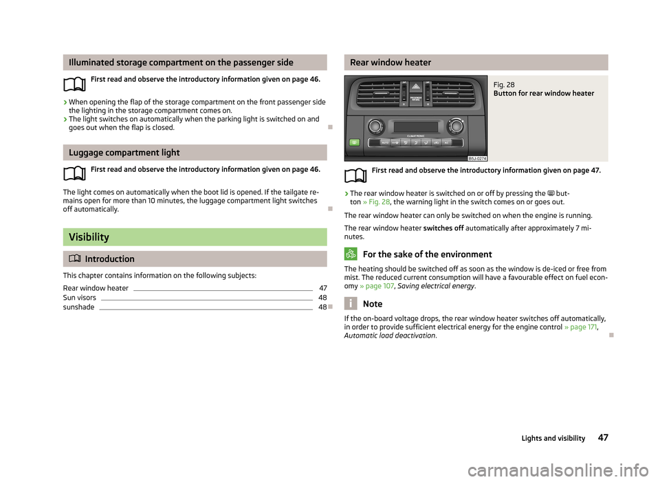
Rear window heaterFig. 28
Button for rear window heater
First read and observe the introductory information given on page 47.
›
The rear window heater is switched on or off by pressing the
but-
ton » Fig. 28 , the warning light in the switch comes on or goes out.
The rear window heater can only be switched on when the engine is running. The rear window heater switches off automatically after approximately 7 mi-
nutes.
For the sake of the environment
The heating should be switched off as soon as the window is de-iced or free from
mist. The reduced current consumption will have a favourable effect on fuel econ-
omy » page 107 , Saving electrical energy .
Note
If the on-board voltage drops, the rear window heater switches off automatically,
in order to provide sufficient electrical energy for the engine control » page 171,
Automatic load deactivation .
47Lights and visibility
Page 54 of 219
Rear window
Introduction
This chapter contains information on the following subjects:
Manually dimmed rear-view mirror
51
Exterior mirrors
51WARNING■ Make sure that the mirror is not covered by ice, snow, condensation or other
objects.■
Convex (curved outward) or aspheric exterior mirrors increase the field of vi-
sion. They do, however, make objects appear smaller in the mirror. These mir-
rors are therefore only of limited use for estimating distances to the following vehicles.
■
Whenever possible use the interior mirror for estimating the distances to
the following vehicles.
Manually dimmed rear-view mirror
First read and observe the introductory information and safety warn-ings
on page 51.
Basic setting
›
Pull the lever on the lower edge of the mirror away from the windscreen.
Dimming mirror
›
Push the lever on the lower edge of the mirror towards the windscreen.
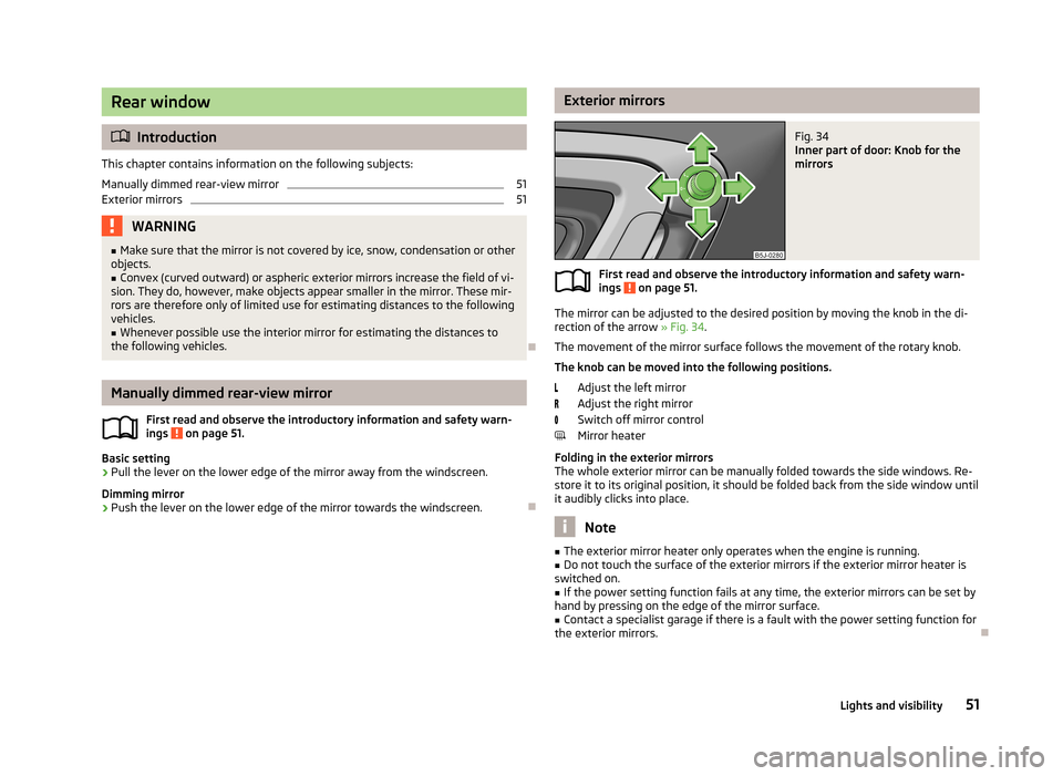
Exterior mirrorsFig. 34
Inner part of door: Knob for the
mirrors
First read and observe the introductory information and safety warn-
ings on page 51.
The mirror can be adjusted to the desired position by moving the knob in the di-
rection of the arrow » Fig. 34.
The movement of the mirror surface follows the movement of the rotary knob.
The knob can be moved into the following positions.
Adjust the left mirror
Adjust the right mirror
Switch off mirror control
Mirror heater
Folding in the exterior mirrors
The whole exterior mirror can be manually folded towards the side windows. Re- store it to its original position, it should be folded back from the side window until
it audibly clicks into place.
Note
■ The exterior mirror heater only operates when the engine is running.■Do not touch the surface of the exterior mirrors if the exterior mirror heater is
switched on.■
If the power setting function fails at any time, the exterior mirrors can be set by
hand by pressing on the edge of the mirror surface.
■
Contact a specialist garage if there is a fault with the power setting function for
the exterior mirrors.
51Lights and visibility
Page 56 of 219
Adjusting the front seatsFig. 35
Control elements at the seat
First read and observe the introductory information and safety warn-
ings on page 52.
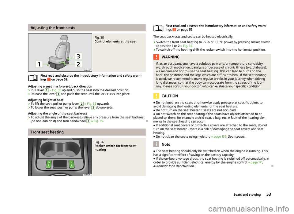
Adjusting a seat in a forward/back direction
›
Pull lever
1
» Fig. 35 up and push the seat into the desired position.
›
Release the lever
1
and push the seat until the lock clicks into place.
Adjusting height of seat
›
To lift the seat, pull or pump lever
2
» Fig. 35 upwards.
›
To lower the seat, push or pump the lever
2
downwards.
Adjusting the angle of the seat backrest
›
To adjust the angle of the backrest, relieve any pressure from the seat backrest
(do not lean on it) and turn handwheel
3
» Fig. 35 .
Front seat heating
Fig. 36
Rocker switch for front seat
heatingFirst read and observe the introductory information and safety warn-
ings on page 52.
The seat backrests and seats can be heated electrically.
›
Switch the front seat heating to 25 % or 100 % power by pressing rocker switch
at position 1 or 2 » Fig. 36 .
›
To switch off the heating shift the rocker switch into the horizontal position.
WARNINGIf, as an occupant, you have a subdued pain and/or temperature sensitivity,
e.g. through medication, paralysis or because of chronic illness (e.g. diabetes),
we recommend not to use the seat heating. This can lead to burns on the
back, the posterior and the legs which are difficult to heal. If the seat heating
is used, we recommend to make regular breaks in your journey when driving
long distances, so that the body can recuperate from the stress of the jour- ney. Please consult your doctor, who can evaluate your specific condition.
CAUTION
■ Do not kneel on the seats or otherwise apply pressure at specific points to
avoid damaging the heating elements for the seat heaters.■
Do not turn on the seat heater if seats are not occupied.
■
Do not switch on the seat heating if the seats have objects attached to or
placed on them, for example a child seat, a bag, etc. A fault of the heating ele- ments in the seat heating can occur.
■
If additional seat covers or protective covers are attached to the seats, do not
turn on the seat heater - there is a risk of damaging the seat covers and seat
heating.
■
Do not clean the seats using moisture » page 156, Seat covers .
Note
■
The seat heating should only be switched on when the engine is running. This
has a significant effect of saving on the battery capacity.■
If the on-board voltage drops, the seat heating is switched off automatically, in
order to provide sufficient electrical energy for the engine control » page 171,
Automatic load deactivation .
53Seats and stowing
Page 61 of 219
WARNING (Continued)■Please note that transporting heavy objects alters the handling properties
of the vehicle due to the displacement of the centre of gravity – risk of acci-
dent! The speed and style of driving must be adjusted accordingly.■
If the items of luggage or objects are attached to the lashing eyes with un-
suitable or damaged lashing straps, injuries can occur in the event of braking
manoeuvres or accidents. To prevent items of luggage from being thrown for-
ward, always use suitable lashing straps which must be firmly attached to the lashing eyes.
■
The transported items must be stowed in such a way that no objects are
able to slip forward on sudden driving or braking manoeuvres – risk of injury!
■
When transporting fastened objects which are sharp and dangerous in the
boot that has been enlarged by folding the rear seats forward, ensure the safety of the passengers transported on the other rear seats » page 125, Cor-
rect seated position for the passengers in the rear seats .
■
If the rear seat next to the folded forward seat is occupied, ensure maxi-
mum safety, e.g. by placing the goods to be transported in such a way that the
seat is prevented from folding back in case of a rear collision.
■
Never drive with the luggage compartment lid open or ajar, as otherwise ex-
haust gases may get into the interior of the vehicle – risk of poisoning!
■
Under no circumstances should the permissible axle loads and the permissi-
ble total vehicle weight be exceeded – risk of accident!
■
Never transport people in the boot!
CAUTION
Please ensure that the heating elements for the rear window heater are not dam-
aged as a result of abrasive objects.
Note
Tyre pressure must be adjusted to the load » page 173, Service life of tyres .
Class N1 vehicles
First read and observe the introductory information and safety warn-
ings
on page 57.
On class N1 vehicles, which are not fitted with a protective grille, a lashing set which complies with the standard EN 12195 (1 - 4) must be used for fastening the
load.
The proper functioning of the electrical system is essential for the safe operation
of the vehicle. It is important to ensure that it is not damaged during modifica-
tions or when loading or unloading the luggage compartment.
Fastening elements
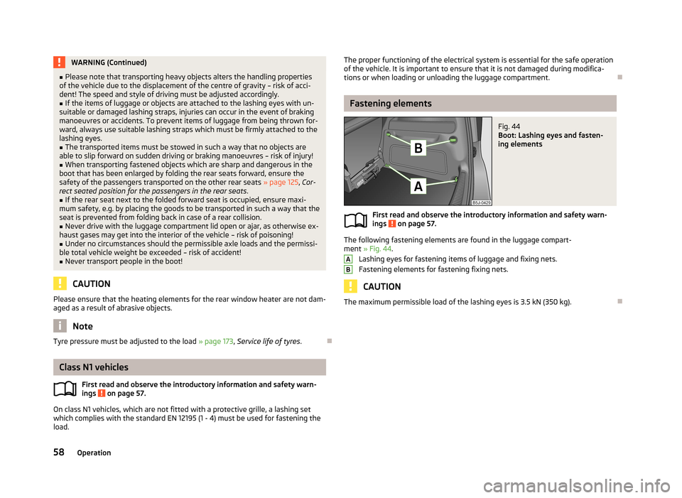
Fig. 44
Boot: Lashing eyes and fasten-
ing elements
First read and observe the introductory information and safety warn-
ings on page 57.
The following fastening elements are found in the luggage compart-
ment » Fig. 44 .
Lashing eyes for fastening items of luggage and fixing nets.
Fastening elements for fastening fixing nets.
CAUTION
The maximum permissible load of the lashing eyes is 3.5 kN (350 kg).
AB58Operation
Page 63 of 219
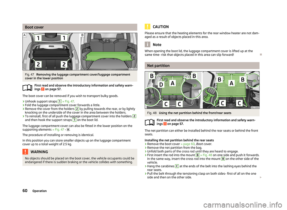
Boot coverFig. 47
Removing the luggage compartment cover/luggage compartment
cover in the lower position
First read and observe the introductory information and safety warn-
ings
on page 57.
The boot cover can be removed if you wish to transport bulky goods.
›
Unhook support straps
1
» Fig. 47 .
›
Fold the luggage compartment cover forwards a little.
›
Remove the cover from the holders
2
by pulling towards the rear, or by lightly
knocking on the underside of the cover in the area between the holders.
›
To reinstall, first of all push the luggage compartment cover into the holders
2
and then hook the support straps
1
on the boot lid.
The luggage compartment cover can also be fitted in the lower position on the
supporting elements » Fig. 47 -
.
The procedure of installing or removing is identical. In this position you can store smaller objects up on the luggage compartment cover up to a total weight of 2.5 kg.
WARNINGNo objects should be placed on the boot cover, the vehicle occupants could be
endangered if there is sudden braking or the vehicle collides with something.CAUTIONPlease ensure that the heating elements for the rear window heater are not dam-
aged as a result of objects placed in this area.
Note
When opening the boot lid, the luggage compartment cover is lifted up at the
same time- risk that objects placed in this area can slip forward!
Net partition
Fig. 48
Using the net partition behind the front/rear seats
First read and observe the introductory information and safety warn-
ings
on page 57.
The net partition can either be installed behind the rear seats or behind the front
seats.
Installing the net partition behind the rear seats
›
Remove the boot cover » page 60, Boot cover .
›
Remove the net partition from the bag.
›
Unfold both parts of the cross rod until they are heard to engage.
›
First insert the rod into the mount
B
» Fig. 48 on one side and push it forwards.
In the same way, insert the cross rod into the mount
B
on the other side of the
vehicle.
›
Hang the carabines
C
at the ends of the belt into the lashing eyes behind the
rear seats.
›
Pull the belt through the tensioning clasp on both sides- first of all on the one side and then on the other side.
60Operation
Page 159 of 219
CAUTION■Do not use leather cleaners on Alcantara ®
seat upholstery.■Do not use solvents, floor wax, shoe cream, stain remover or similar agents on
Alcantara ®
seat upholstery.■
Avoid leaving the vehicle in bright sunlight for long periods of time in order to
stop the fabric from bleaching. If the vehicle is parked outside for long periods of
time, cover the fabric to protect it from direct sunlight.
■
Some clothing materials, e.g. dark denim, do not have sufficient colour fastness.
This can cause damage or clearly visible discolouration to seat covers, even when used correctly. This applies particularly to light-coloured seat covers. This does
not relate to a fault in the seat cover, but rather to poor colour fastness of the clothing textiles.
Seat covers
First read and observe the introductory information and safety warn-
ings
on page 154.
Electrically heated seats
Do not clean the covers by moistening, as this can damage the seat heating sys-
tem.
Use a specific cleaning agent such as dry foam or similar to clean the covers.
Seats without seat heating
Thoroughly vacuum the seat covers with a vacuum cleaner before cleaning.
Clean the seat covers with a damp cloth or cleaning products specially designed for this purpose.
Indented points arising on the fabrics by everyday use, can be removed by brush- ing against the direction of hair with a damp brush.
Always clean all parts of the covers, so that there are no visible edges. Then allow the seat to dry completely.
CAUTION
■ Regularly remove dust from the seat covers using a vacuum cleaner.■Electrically heated seats must not be dried after cleaning by switching on the
heater.■
Do not sit on wet seats - risk of seat deformation.
■
Always clean the seats “from seam to seam”.
Seat belts
First read and observe the introductory information and safety warn-
ings
on page 154.
The belt webbing must always be kept clean.
Wash dirty seat belts with mild soapy water.
Remove coarse dirt with a soft brush.
Dirty belt webbing may impair the correct functioning of the inertia reel.
WARNING■ The seat belts must not be removed for cleaning.■Never clean the seat belts chemically as chemical cleaning products could
destroy the fabric.■
The seat belts must not be allowed to come into contact with corrosive liq-
uids (e.g. acids).
■
Check the condition of all the seat belts on a regular basis. If any damage to
the belt webbing, seat belt connections, inertia reel or lock is detected, the
seat belt must be replaced by a specialist garage.
■
The seat belts must be fully dried before being rolled up.
156General Maintenance
Page 168 of 219

The oil level must be checked at regular intervals. We recommend it be checked
after each time you refuel or prior to making a long journey.
We recommend maintaining the oil level within the range A
, but not above , if
the engine has been operating at high loads, for example, during a lengthy motor-
way trip during the summer months, towing a trailer or negotiating a high moun- tain pass.
The warning light in the instrument cluster will indicate whether the oil level is too low » page 21 , Engine oil . Check the oil level using the dipstick as soon
as possible. Add oil accordingly.
CAUTION
The oil level must on no account be above range A » Fig. 130 . Risk of damaging
the exhaust system!
Note
Engine oil specifications » page 163.
Replenishing
First read and observe the introductory information and safety warn-
ings
on page 163.
›
Check the oil level » page 164.
›
Unscrew the cap of the engine oil filler opening.
›
Replenish the oil in portions of 0.5 litres in accordance with the correct specifi-
cations » page 163 , Specifications and capacity .
›
Check the oil level » page 164.
›
Carefully screw on the oil filler opening cap and push the dipstick in fully.
Changing
First read and observe the introductory information and safety warn-ings
on page 163.
The engine oil must be changed at specified service intervals » page 144 or ac-
cording to the service interval display » page 16, Service Interval Display .
Coolant
Introduction
This chapter contains information on the following subjects:
Capacity
166
Checking the coolant level
166
Replenishing
167
The coolant consists of water with coolant additive. This mixture guarantees anti- freeze protection, protects the cooling/heater system against corrosion and pre-
vents lime formation.
Vehicles exported to countries with a mild climate are already factory-filled with
a coolant which offers antifreeze protection down to about -25 ℃. In these coun-
tries, the concentration of coolant additive should be at least 40%.
Vehicles exported to countries with a cold climate are already factory-filled with a
coolant which offers antifreeze protection down to about -35 °C. In these coun-
tries, the concentration of coolant additive should be at least 50%.
If a higher concentration of antifreeze is required for climatic reasons, the con-centration of coolant additive can be increased up to a maximum of 60% (anti-
freeze protection down to approx. -40 °C).
When refilling, only use the same antifreeze identified on the coolant expansion
vessel » Fig. 131 on page 166.
WARNING■
The engine compartment of your car is a hazardous area. The following
warning instructions must be followed at all times when working in the en-
gine compartment » page 159.■
Do not continue your journey if for some reason it is not possible to top
up the coolant under the prevailing conditions! Switch off the engine and seek
assistance from a specialist garage.
CAUTION
■ The concentration of coolant additive in the coolant must never be under 40%.■Over 60% of coolant additive in the coolant reduces the antifreeze protection
and cooling effect. 165Inspecting and replenishing