2013 SKODA OCTAVIA towing
[x] Cancel search: towingPage 239 of 287

Fire extinguisherFig. 196
Fire extinguisher
First read and observe the introductory information given on page 235.
The fire extinguisher is attached by two straps in a holder underneath the driver's
seat.
Removing/attaching
›
Loosen the two straps by pulling the buckles in the direction of the ar- row » Fig. 196 .
›
Remove the fire extinguisher.
Follow these steps in the reverse order for attachment.
Please read carefully the instructions which are attached to the fire extinguish-
er.
The fire extinguisher must be checked by an authorised person once a year. The
national legal requirements must be observed.
WARNINGThe fire extinguisher must always be secured safely so that they do not come loose when making an emergency braking or in a vehicle collision which could
cause injuries to occupants.
Note
■ The fire extinguisher must comply with national legal requirements.■Pay attention to the expiration date of the fire extinguisher. If the fire extin-
guisher is used after the expiration date, its proper function is not assured.■
The fire extinguisher is part of the scope of delivery in certain countries only.
Vehicle tool kitFig. 197
Vehicle tool kit
First read and observe the introductory information given on page 235.
The vehicle tool kit and the lifting jack are housed in a plastic box in the spare wheel or in the storage space for the spare wheel. There is also space here for
the removable ball rod for the trailer towing device. The box is attached with a
strap on the spare wheel.
The components of the vehicle tool kit (depending on vehicle equip- ment) » Fig. 197 .
Screwdriver
Key for removing and installing the tail light
Adapter for anti-theft wheel bolts Towing eye
Clamps for removing the wheel trims
Car jack
Crank for the jack
Wheel wrench
Extraction pliers for wheel bolt caps Replacement bulb set
Screw the jack back into its home position after use to allow you to store it in the
box with the toolkit.
12345678910236Do-it-yourself
Page 247 of 287

Both batteries must have a rated voltage of 12 V. The capacity (Ah) of the battery
supplying the power must not be significantly less than the capacity of the dis-
charged battery in your vehicle.
Jump-start cables
Only use jump-start cables which have an adequately large cross-section and in-
sulated terminal clamps. Observe the instructions of the jumper lead manufactur-
er.
Positive cable – colour coding in the majority of cases is red.
Negative cable – colour coding in the majority of cases is black.
Jump-starting in vehicles with the START-STOP system
Fig. 204
Engine earth: START-STOP sys-
tem
First read and observe the introductory information and safety warn- ings on page 243.
On vehicles with the START-STOP system, the jump-start cable of the charger
must never be connected directly to the negative pole of the vehicle battery, but
only to the engine earth » Fig. 204.
Towing the vehicle
Introduction
This chapter contains information on the following subjects:
Front towing eye
245
Rear towing eye
245
Vehicles with a tow hitch
246Vehicles with manual transmission may be towed in with a tow bar or a tow rope
or with the front or rear wheels raised.
Vehicles with automatic transmission may be towed in with a tow bar or a tow
rope or with the front wheels raised. If the vehicle is raised at rear, the automatic
gearbox is damaged!
A tow bar is the safest way of towing a vehicle and also minimises any shocks.
Only use a tow rope if a suitable tow bar is not available.
When towing, the following guidelines must be observed.
Driver of the tow vehicle›
Release the clutch particularly gently when starting off or depress the accelera-
tor particularly gently if the vehicle is fitted with an automatic gearbox.
›
On vehicles with a manual transmission, only push down on the accelerator
pedal once the rope is taught.
The maximum towing speed is 50 km/h.
Driver of the towed vehicle
›
Switch on the ignition so that the steering wheel is not blocked and so that the
turn signal lights, horn, windscreen wipers and windscreen washer system can be used.
›
Take the vehicle out of gear or move the selector lever into position N if the ve-
hicle is fitted with an automatic gearbox.
Please note that the brake servo unit and power steering only operate if the en-
gine is running. If the engine is not running, significantly more physical force is re- quired to depress the brake pedal and steer the vehicle.
If using a tow rope, ensure that it is always kept taught.
CAUTION
■ Do not tow start the engine – there is a risk of damaging the engine and the
catalytic converter. The battery from another vehicle can be used as a jump-start
aid » page 243 , Jump-starting .■
If the gearbox no longer contains any oil because of a defect, your vehicle must
only be towed with the driven wheels raised clear of the ground or on a special
breakdown vehicle or trailer.
■
The vehicle must be transported on a special breakdown vehicle or trailer if it is
not possible to tow in the vehicle in the way described or if the towing distance is
greater than 50 km.
■
To protect both vehicles when tow-starting or towing, the tow rope should be
elastic. Thus one should only use plastic fibre rope or a rope made out of a simi-
larly elastic material.
244Do-it-yourself
Page 248 of 287
■While towing, take care to avoid impermissibly high tensile forces or jerky loads.
There is always a risk of excessive stresses and damage resulting at the points to which you attach the tow rope or tow bar when you attempt to tow a vehicle
which is not standing on a paved road.■
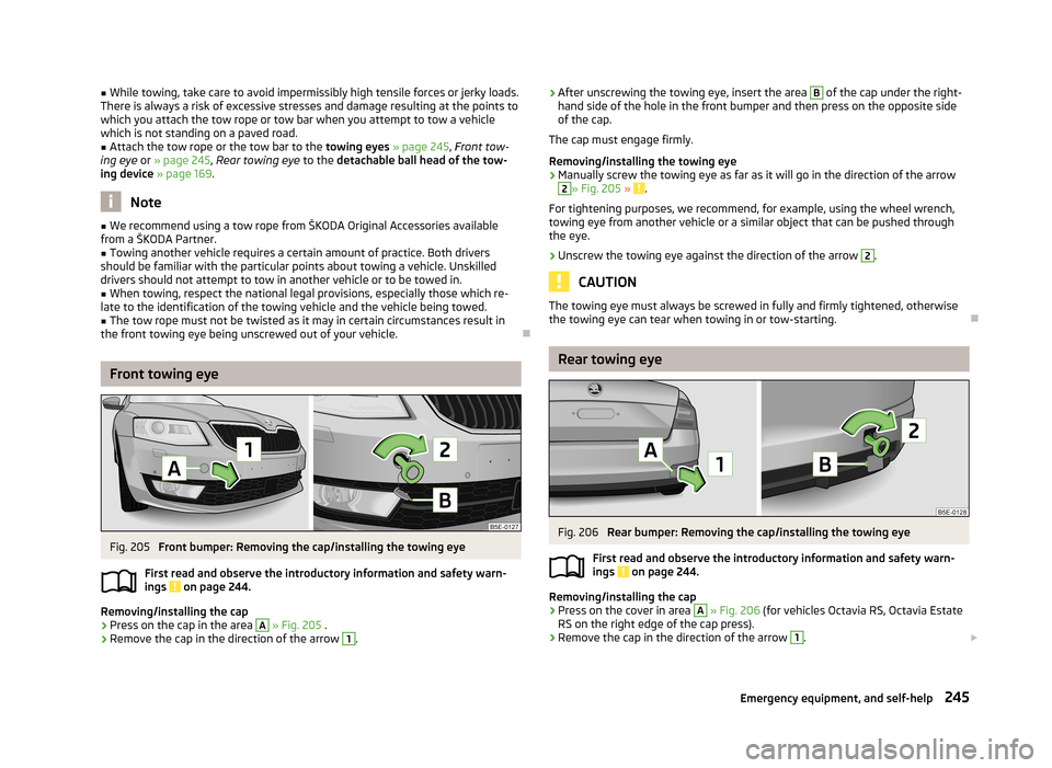
Attach the tow rope or the tow bar to the towing eyes » page 245 , Front tow-
ing eye or » page 245 , Rear towing eye to the detachable ball head of the tow-
ing device » page 169 .
Note
■
We recommend using a tow rope from ŠKODA Original Accessories available
from a ŠKODA Partner.■
Towing another vehicle requires a certain amount of practice. Both drivers
should be familiar with the particular points about towing a vehicle. Unskilled
drivers should not attempt to tow in another vehicle or to be towed in.
■
When towing, respect the national legal provisions, especially those which re-
late to the identification of the towing vehicle and the vehicle being towed.
■
The tow rope must not be twisted as it may in certain circumstances result in
the front towing eye being unscrewed out of your vehicle.
Front towing eye
Fig. 205
Front bumper: Removing the cap/installing the towing eye
First read and observe the introductory information and safety warn- ings
on page 244.
Removing/installing the cap
›
Press on the cap in the area
A
» Fig. 205 .
›
Remove the cap in the direction of the arrow
1
.
›After unscrewing the towing eye, insert the area B of the cap under the right-
hand side of the hole in the front bumper and then press on the opposite side
of the cap.
The cap must engage firmly.
Removing/installing the towing eye›
Manually screw the towing eye as far as it will go in the direction of the arrow
2
» Fig. 205 » .
For tightening purposes, we recommend, for example, using the wheel wrench,
towing eye from another vehicle or a similar object that can be pushed through
the eye.
›
Unscrew the towing eye against the direction of the arrow
2
.
CAUTION
The towing eye must always be screwed in fully and firmly tightened, otherwise
the towing eye can tear when towing in or tow-starting.
Rear towing eye
Fig. 206
Rear bumper: Removing the cap/installing the towing eye
First read and observe the introductory information and safety warn- ings
on page 244.
Removing/installing the cap
›
Press on the cover in area
A
» Fig. 206 (for vehicles Octavia RS, Octavia Estate
RS on the right edge of the cap press).
›
Remove the cap in the direction of the arrow
1
.
245Emergency equipment, and self-help
Page 249 of 287

›Thread after unscrewing the towing area B of the cover under the upper side
of the hole in the rear bumper (for vehicles Octavia RS, Octavia Combi RS under
the right side of the hole).›
Press on the lower side of the cap (for vehicles Octavia RS, Octavia RS on the left side of the cap press).
The cap must engage firmly.
Removing/installing the towing eye
›
Manually screw the towing eye as far as it will go in the direction of the arrow
2
» Fig. 206 » .
For tightening purposes, we recommend, for example, using the wheel wrench,
towing eye from another vehicle or a similar object that can be pushed through
the eye.
›
Unscrew the towing eye against the direction of the arrow
2
.
CAUTION
The towing eye must always be screwed in fully and firmly tightened, otherwise
the towing eye can tear when towing in or tow-starting.
Vehicles with a tow hitch
First read and observe the introductory information and safety warn-
ings
on page 244.
On vehicles with a factory-fitted towing device, there is no mount for the screw-
in towing eye behind the cap.
Use the built-in detachable ball rod for towing » page 169, Towing device .
Towing the vehicle using the towing device is a viable alternative solution to us-
ing the towing eye.
If the towing device is removed completely, it must be replaced with the standard
reinforcement of the rear bumper which is part of the mount for the towing eye.
If this procedure is not observed, the vehicle may not meet the national legal pro- visions.
CAUTION
The detachable ball rod and/or the vehicle can be damaged if an unsuitable towbar is used.NoteThe detachable ball rod must always be in the vehicle so that it can be used for
towing, if necessary.
Remote control
Introduction
This chapter contains information on the following subjects:
Replacing the battery in the remote control key
247
Synchronising the remote control
247
Replace the battery in the remote control of the auxiliary heater (parking
heater)
247
CAUTION
■ The replacement battery must have the same specification as the original bat-
tery.■
When replacing the battery, pay attention to the correct polarity.
For the sake of the environment
Dispose of the used battery in accordance with national legal provisions.
246Do-it-yourself
Page 266 of 287

Technical data
Technical data
Vehicle data
Introduction
This chapter contains information on the following subjects:
Vehicle identification data
263
Dimensions
265
Vehicle-specific information depending on engine type
267
The details given in the vehicle's technical documentation always take prece-
dence over the details in the Owner's Manual.
The listed performance values were determined without performance-reducing
equipment, e.g. air conditioning system.
Vehicle identification data
Fig. 236
Vehicle data sticker/type plate
First read and observe the introductory information given on page 263.
Vehicle data sticker
The vehicle data sticker » Fig. 236 - is located underneath the floor covering in
the boot.
The vehicle data sticker contains the following data: Vehicle identification number (VIN)
Vehicle type
Gearbox code/paint number/interior equipment/engine output/engine code Partial vehicle description
Operating weight (in kg) Fuel consumption (in ltr./100 km) - intra-urban/extra-urban/combined
CO 2 emission levels - combined (in g/km)
The indicated positions
5
,
6
and
7
on the vehicle data sticker are only valid for
some countries.
Type plate
The type plate » Fig. 236 -
is located at the bottom of the B-pillar on the driv-
er's side.
The type plate lists the following weights: Maximum permissible gross weight
Maximum permissible towed weight (towing vehicle and trailer)
Maximum permissible front axle load
Maximum permissible rear axle load
Vehicle identification number (VIN)
The vehicle identification number - VIN (vehicle body number) is stamped into the
engine compartment on the right hand suspension strut dome. This number is al- so located on a sign on the lower left hand edge below the windscreen (together
with a VIN bar code).
The VIN can also be displayed in Infotainment » Operating instructions for Info-
tainment , chapter Setting vehicle systems (CAR button) .
Engine number
The engine number (three-digit identifier and serial number) is stamped on the engine block.
1234567891011263Technical data
Page 267 of 287

Operating weight
The specified operating weight is for orientation purposes only. This value repre- sents the minimum operating weight without additional weight-increasing equip-ment such as air conditioning system, spare wheel, or trailer hitch.
The operating weight also contains the weight of the driver (75 kg), the weight of
the operating fluids, the tool kit, and a fuel tank filled to 90 % capacity.
It is possible to calculate the approximate loading capacity from the difference
between the permissible total weight and the operating weight »
.
The payload consists of the following components: › Passengers
› All items of luggage and other loads
› Roof load including roof rack system
› Equipment not included in the operating weight
› Trailer hook weight when towing (up to 75 kg and 80 kg for the Octavia Combi
4x4 vehicles).
Fuel consumption and CO 2 emissions according to ECE regulations and EU
directives
The measurement of the intra-urban cycle begins with a cold start of the engine. Afterwards standard urban driving is simulated.
In the extra-urban driving cycle, the vehicle is accelerated and decelerated in all
gears, corresponding to daily routine driving conditions. The driving speed varies
between 0 and -120 km/h.
The calculation of the combined fuel consumption considers a weighting of about 37 % for the intra-urban cycle and 63 % for the extra-urban cycle.
WARNINGDo not exceed the specified maximum permissible weights – risk of accident
and damage!Note■ If required, you can find out the precise weight of your vehicle at a specialist ga-
rage.■
The fuel consumption and emission values have been determined in accordance
with rules and under conditions set out by legal or technical requirements for de-
termining operational and technical data for motor vehicles.
■
Depending on the range of equipment, style of driving, traffic situation, weather
influences and vehicle condition, consumption values may deviate from the indi-
cated values.
264Technical data
Page 278 of 287

Hazard warning light system61
Jump-starting243
Locking the driver's door248
Start engine - KESSY124
Switching off the ignition –KESSY124
Towing the using the tow hitch246
Towing the vehicle244
Tyre repair240
Unlocking the driver's door248
Unlocking the tailgate249
Emergency equipment Fire extinguisher
236
First aid kit235
Jack236
Vehicle tool kit236
Warning triangle235
Emissions263
Engine Running in
130
Engine compartment215
Brake fluid223
Coolant222
Overview218
Vehicle battery224
Engine oil219
Capacity219
Changing221
Checking220
indicator symbol23
Replenishing221
Specifications219
Warning icon23
Environment131
Environmental compatibility134
Environmentally friendly driving131
EPC Warning light
19
ESC Function
137
Warning light18
Exhaust inspection system Warning light19
F
Fastening elements
92
Fatigue detection168
Function168
Information messages168
Films206
Fire extinguisher236
First aid kit235
Floor covering Fixing
94
Fog lights59
Warning light21
Fog lights with CORNER function59
Footmats126
see footmats126
Force limit Power windows
49
Force limiter electric luggage compartment lid (Octavia Estate) 44sliding/tilting roof (Octavia Estate)
52
sliding/tilting roof (Octavia)50
Front airbag187
Front Assist154
Activating/deactivating157
City emergency braking157
Information messages158
Instructions and Information155
Operation156
Radar sensor155
Front door warning light63
Fuel212
Diesel214
Fuel gauge13
refer to Fuel212
Refuelling212
Unleaded petrol213
Warning icon25
Fuel consumption131
fuel filter warning messages
25
Fuses Assignment
251
Assignment of fuses in the dash panel253
Colour coding251
Fuse assignment in the engine compartment254
Plastic clip254
Replacing251
G
Gear change Gear recommendation
27
Information on the selected gear27
Gear changing Gear stick
126
General view Cockpit
9
Glasses storage box86
Glow plug system Warning light
19
H
Handbrake
125
Warning light16
Hazard warning light system61
HBA139
Head airbag189
Headlight assist58
Warning icon25
Headlight cleaning system Headlight cleaning system
67
Headlights Bulb arrangement
256
Driving abroad136
Headlight cleaning system67
Head restraint73
275Index
Page 280 of 287

Headlight flasher56
Low beam55
Main beam56
Parking lights61
Rear fog light60
Side lights55
Switching on/off55
Turn signal56
Warning lights15
Lights on/off55
Loads263
Locking Individual settings
39
KESSY38
Key36
Remote control37
Vehicle key36
Locking and unlocking the vehicle from the inside 39
Long-cargo channel
90
Low beam55
Luggage compartment91
Compartment with cargo element98
Cover95
double sided floor covering94
Emergency unlocking249
Fastening elements92
Fix floor covering94
Fixing nets93
Foldable hooks (Octavia Estate)94
Folding double hooks93
Lighting91
Luggage net95
Multifunction box (Octavia Estate)99
Roll-up luggage compartment cover (Octavia Es- tate)
96
Storage compartments under the floor covering98
Stowing roll-up luggage compartment cover97
Stowing roof racks97
Unlocking the tailgate249
Variable loading floor99
Luggage compartment cover95
Luggage compartment cover (Octavia Estate)96
Luggage compartment lid43
Luggage net95
M
Main beam
56
Warning light21
Maintenance134
Decorative films206
Manual air conditioning adjusting
111
Recirculated air mode111
Manual gear changing see gear changing
126
Manually setting air conditioning Control elements
110
Materials defect liability5
MAXI DOT display31
Lap timer32
Main menu32
Operation26
Stop watch32
MAXI DOT see MAXI DOT display
31
Memory29
Mirror Exterior mirrors
69
Mirrors Interior mirror
69
Vanity65
Modes of the automatic transmission127
Modifications200
Modifications and technical alterations Airbags
203
Service201
Spoiler202
Motor warning messages
22
Multicollision brake140
Multifunction box (Octavia Estate)99
Multifunction display Functions
29
Information29
Memory29
Operation26
N
N1
92
Net partition101
Behind the front seats103
Behind the rear seats102
Removing and refitting the housing103
Nets93
O
Oil See Engine oil
220
warning messages23
Oil pressure warning messages
23
Onboard computer see multifunction display
29
Operation in winter De-icing windows
207
Diesel fuel214
Vehicle battery226
Outside temperature27
Overview Engine compartment
218
Warning icons21
Warning lights15
P
Paintwork See Paintwork care
205
Paintwork care205
277Index