2013 SKODA FABIA towing
[x] Cancel search: towingPage 148 of 223
General Maintenance
Car care
Service intervals
Introduction
This chapter contains information on the following subjects:
Overview of service intervals
145
Fixed service intervals QI1 - QI4
146
Variable service interval QI6
146
Information about the ŠKODA service
146
The Service Interval Display in the instrument cluster will remind you to have ev- ery service specified by the manufacturer at the right time so that you never for- get a service.
A timely and adequate performance of servicing works is one of the requirements for the settlement of possible warranty claims.
The completion of services can be verified through the confirmed service certifi-
cation and the corresponding receipts.
The service intervals are appropriate for normal operating conditions.
In case of difficult operating conditions, it is necessary to have some servicing
work performed before the date of the next service or between the service inter- vals stated. This applies mainly to the cleaning or the replacement of the air filter
insert in regions with heavy dust pollution as well as checking and replacing the
toothed belt, but also vehicles with diesel particle filter which can use the engine
oil more intensely.
These severe conditions are:
› fuel containing sulphur;
› frequent short trips;
› longer idling mode of the engine (e.g. taxi vehicles);
› operation in areas with heavy dust pollution;
› frequent trailer towing;
›
predominantly stop-and-go traffic as tends to occur in city driving, for example;
› operation predominantly during winter.
A service adviser at the specialist garage will tell you whether your vehicle's oper- ating conditions make it necessary for such work to be carried out between the
normal service intervals.
Different service charges may apply, depending on the scope of necessary works
as well as the model, features and condition of your vehicle.
Note
■ The customer is responsible for covering the cost of all services including
changing or replenishing the operating fluid, even during the warranty period, un-
less the ŠKODA AUTO a.s. warranty terms or other agreements state otherwise.■
You will be informed about the scope of the service with regard to a particular
service event by the specialist garage.
Overview of service intervals
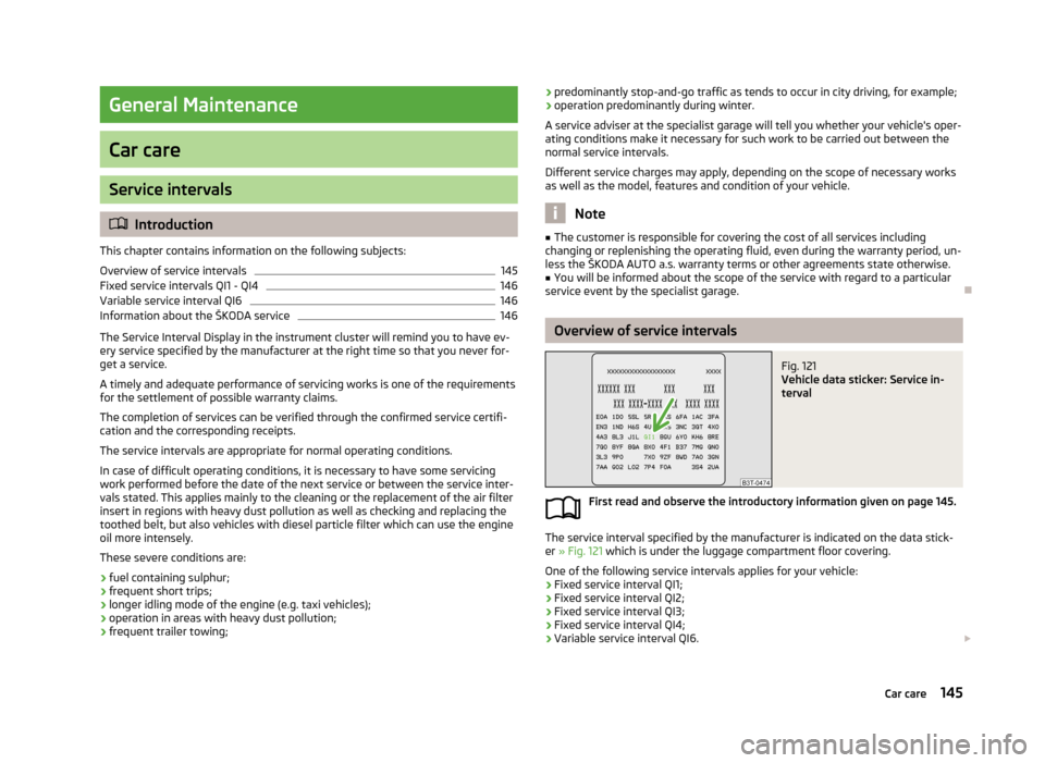
Fig. 121
Vehicle data sticker: Service in-
terval
First read and observe the introductory information given on page 145.
The service interval specified by the manufacturer is indicated on the data stick-
er » Fig. 121 which is under the luggage compartment floor covering.
One of the following service intervals applies for your vehicle: › Fixed service interval QI1;
› Fixed service interval QI2;
› Fixed service interval QI3;
› Fixed service interval QI4;
› Variable service interval QI6.
145Car care
Page 169 of 223

The oil level must be checked at regular intervals. We recommend it be checked
after each time you refuel or prior to making a long journey.
We recommend maintaining the oil level within the range A
, but not above , if
the engine has been operating at high loads, for example, during a lengthy motor-
way trip during the summer months, towing a trailer or negotiating a high moun- tain pass.
The warning light in the instrument cluster will indicate whether the oil level is too low » page 21 , Engine oil . Check the oil level using the dipstick as soon
as possible. Add oil accordingly.
CAUTION
■ Always check the oil level on vehicles with the 1.2 l/44 kW engine when the en-
gine is cold. Otherwise the measuring result is incorrect und oil could be incor-
rectly replenished - risk of engine damage!■
The oil level must never be above the
A
range » Fig. 127 – there is a risk of
damaging the exhaust system.
Note
Engine oil specifications » page 164.
Replenishing
First read and observe the introductory information and safety warn-
ings
on page 164.
›
Check the oil level » page 165.
›
Unscrew the cap of the engine oil filler opening.
›
Replenish the oil in portions of 0.5 litres in accordance with the correct specifi-
cations » page 164 .
›
Check the oil level » page 165.
›
Carefully screw on the oil filler opening cap and push the dipstick in fully.
Changing
First read and observe the introductory information and safety warn-ings
on page 164.
The engine oil must be changed at specified service intervals » page 145 or ac-
cording to the service interval display » page 16, Service Interval Display .
Coolant
Introduction
This chapter contains information on the following subjects:
Capacity
167
Checking the coolant level
167
Replenishing
168
The coolant consists of water with a concentration of coolant additive. This mix-
ture guarantees antifreeze protection, protects the cooling/heater system
against corrosion and prevents the formation of scale.
Vehicles exported to countries with a mild climate are already factory-filled with
a coolant which offers antifreeze protection down to about -25 ℃. In these coun-
tries the concentration of coolant additive should be at least 40 %.
Vehicles exported to countries with a cold climate are already factory-filled with a
coolant which offers antifreeze protection down to about -35 °C. In these coun-
tries the concentration of coolant additive should be at least 50 %.
If a higher concentration of antifreeze is required for climatic reasons, the amount
of coolant additive can only be increased up to a maximum of 60 % (antifreeze
protection down to approx. -40 °C).
When refilling, only use the same antifreeze identified on the coolant expansion vessel » Fig. 128 on page 167.
166General Maintenance
Page 179 of 223

530 kg
545 kg
615 kg
630 kg
650 kg
Speed symbol
This indicates the maximum permissible speed for a vehicle fitted with tyres in
the category concerned.
170 km/h
180 km/h
190 km/h
200 km/h
210 km/h
240 km/h
270 km/h
CAUTION
The information about the load index and the speed symbol for your vehicle are
listed in your vehicle documents.
Unidirectional tyres
First read and observe the introductory information and safety warn-
ings
on page 173.
The direction of rotation of the tyres is marked by arrows on the wall of the tyre.
The direction of rotation indicated must be complied with to obtain the best ben- efits from the characteristics of these tyres.
These characteristics are principally the following.
› Increased driving stability.
› Reduced risk of aquaplaning.
› Reduced tyre noise and reduced tyre wear.
8687919293RSTUHVWTyre pressure monitorFig. 134
Button for setting the tyre infla-
tion pressure control value
First read and observe the introductory information and safety warn-
ings on page 173.
System settings
A system configuration must be run as follows after adjusting the tyre pressure,
after changing one or more wheels, changing the position of a wheel on the vehi- cle (e.g. swapping the wheels between the axles) or when the warning light lights
up while driving.
›
Inflate all the tyres to the specified pressure » page 26,
Tyre pressure .
›
Switch on the ignition.
›
Press the
» Fig. 134 button for more than 2 seconds.
There is a fault in the system if the
warning light comes on and does not go
out after the system configuration.
There is a system fault if the
warning light flashes.
Tyre pressure indicator
The
warning light comes on in any of the following cases.
› The tyre pressure is low.
› The structure of the tyre is damaged.
› The vehicle is loaded on one side.
› The wheels of one axle are loaded more heavily (e.g. when towing a trailer or
when driving uphill or downhill).
› Snow chains are fitted.
› The spare wheel is fitted.
› One wheel per axle was changed.
176General Maintenance
Page 180 of 223

WARNING■When the warning light illuminates, immediately reduce the speed and
avoid sudden steering and brake manoeuvres. Stop the vehicle as soon as
possible and inspect the tyres and their inflation pressure.■
Under certain circumstances (e.g. sporty style of driving, wintry or unpaved
roads) the warning light can be delayed or does not light up at all.
CAUTION
■
The tyre control display does therefore not replace the regular tyre inflation
pressure control, as the system cannot detect an even loss of pressure.■
The system cannot warn in case of very rapid loss of tyre pressure, e.g. in the
event of a sudden puncture. In this case carefully bring the vehicle to a standstill without sudden steering movements or sharp braking.
■
The basic setting must be repeated every 10,000 km or once a year to ensure
proper functioning of the tyre pressure monitor.
Spare wheel
Fig. 135
Boot: Spare wheel
First read and observe the introductory information and safety warn-
ings on page 173.
The spare wheel is located in a well under the floor covering in the luggage com-
partment and held by a special nut » Fig. 135.
Taking the wheel out
›
Open the tailgate.
›
Lift up the floor in the luggage compartment.
›
Remove the box with the tool kit.
›
Unscrew the nut » Fig. 135 anticlockwise.
›Take out the wheel.
Stowing the wheel›
Stow the replaced wheel in the spare wheel well with the rim facing down.
›
Screw on the nut » Fig. 135 clockwise until the wheel is safely secured.
›
Replace the box with the tool kit into the spare wheel and secure it with the
tape.
›
Fold back the floor in the luggage compartment.
›
Close the tailgate.
Install a wheel of the appropriate version and dimensions as soon as possible.
If the dimensions or design of the spare wheel differ from the tyres fitted to the
vehicle (e.g. winter tyres or low-profile tyres), it must only be used briefly in the
event of a puncture and if an appropriately cautious style of driving is adop-
ted »
.
Temporary spare wheel
A yellow warning label is displayed on the rim of the temporary spare wheel.
Please note the following if you intend to use the temporary spare wheel. › The warning label must not be covered after installing the wheel.
› Be specially attentive when driving.
› The pressure for the temporary spare wheel is identical to the maximum pres-
sure of the standard tyres.
› Only use this temporary spare wheel to reach the nearest specialist garage
since it is not intended for permanent use.
WARNING■ Never use the temporary spare wheel if it is damaged.■If the dimensions or design of the temporary spare wheel differ from the fit-
ted tyres, never drive faster than 80 km/h (or 50 mph).■
Avoid accelerating at full throttle, sharp braking and fast cornering.
CAUTION
Observe the instructions on the warning sign of the temporary spare wheel.
177Wheels
Page 184 of 223

Note■The fire extinguisher must comply with national legal requirements.■Pay attention to the expiration date of the fire extinguisher. Proper functioning
of the fire extinguisher is not assured once it has passed its expiry date.■
The fire extinguisher is part of the scope of delivery in certain countries only.
Vehicle tool kit
Fig. 140
Vehicle tool kit
First read and observe the introductory information given on page 180.
The vehicle tool kit and the jack are housed in a plastic box in the spare wheel or
in the storage space for the spare wheel. There is also space here for the remova-
ble ball rod for the trailer towing device. The box is attached with a strap on the spare wheel.
The components of the vehicle tool kit (depending on equipment) » Fig. 140.
Screwdriver
Adapter for anti-theft wheel bolts
Towing eye
Wire tool for removing the full wheel trims
Car jack
Wheel brace
123456Tool for removing wheel bolt caps
Replacement bulb set
Screw the car jack back to its initial position after use to store it back in the box with the vehicle tool kit.WARNING■ The factory-supplied lifting jack is only intended for your model of vehicle.
Under no circumstances attempt to lift heavier vehicles or other loads – there
is a risk of injury.■
Ensure that the vehicle tool kit is safely secured in the boot.
■
Ensure that the box is always secured with the strap.
Changing a wheel
Introduction
This chapter contains information on the following subjects:
Preparation
182
Changing a wheel
182
Subsequent steps
183
Loosening/tightening wheel bolts
183
Raising the vehicle
184
Securing wheels against theft
184WARNING■ If you are in flowing traffic, switch on the hazard warning lights and set up
the warning triangle at the prescribed distance. National legal requirements
must be observed.■
Park the vehicle as far away as possible from the flow of traffic. Park on as
flat and firm a surface as possible.
■
If the vehicle has been retrofitted with tyres which are different from those
it was fitted with at the works, follow these guidelines » page 175, New tyres .
78181Emergency equipment, and self-help
Page 192 of 223
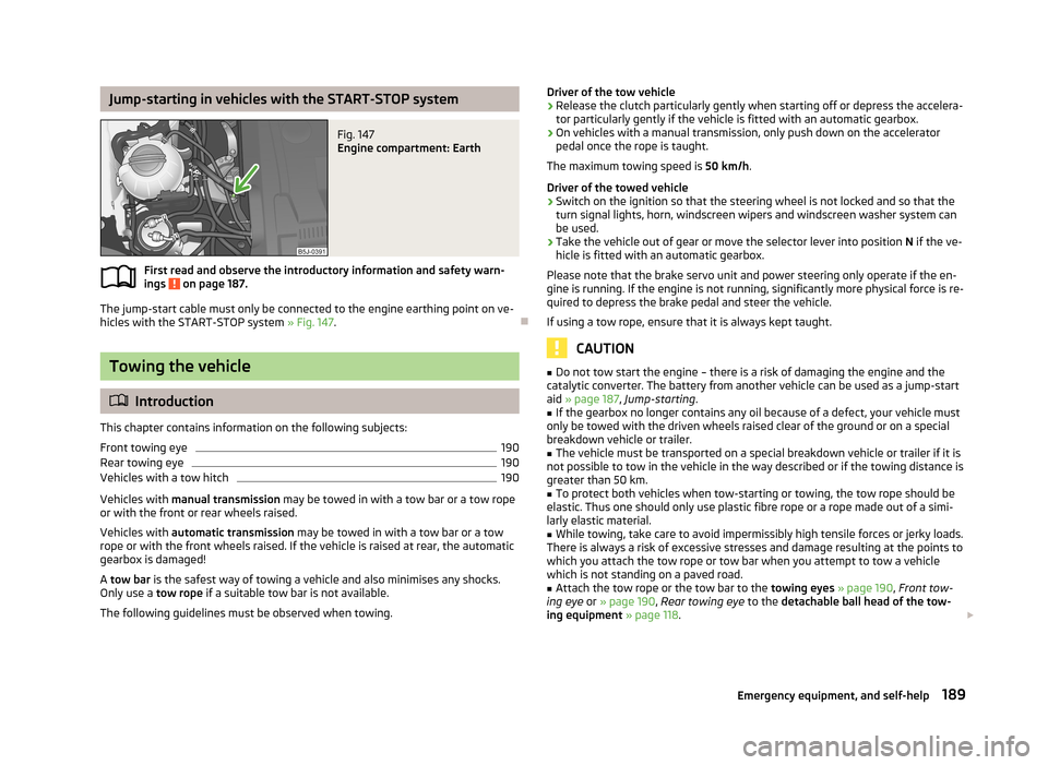
Jump-starting in vehicles with the START-STOP systemFig. 147
Engine compartment: Earth
First read and observe the introductory information and safety warn-ings on page 187.
The jump-start cable must only be connected to the engine earthing point on ve-
hicles with the START-STOP system » Fig. 147.
Towing the vehicle
Introduction
This chapter contains information on the following subjects:
Front towing eye
190
Rear towing eye
190
Vehicles with a tow hitch
190
Vehicles with manual transmission may be towed in with a tow bar or a tow rope
or with the front or rear wheels raised.
Vehicles with automatic transmission may be towed in with a tow bar or a tow
rope or with the front wheels raised. If the vehicle is raised at rear, the automatic
gearbox is damaged!
A tow bar is the safest way of towing a vehicle and also minimises any shocks.
Only use a tow rope if a suitable tow bar is not available.
The following guidelines must be observed when towing.
Driver of the tow vehicle›Release the clutch particularly gently when starting off or depress the accelera-
tor particularly gently if the vehicle is fitted with an automatic gearbox.›
On vehicles with a manual transmission, only push down on the accelerator pedal once the rope is taught.
The maximum towing speed is 50 km/h.
Driver of the towed vehicle
›
Switch on the ignition so that the steering wheel is not locked and so that the turn signal lights, horn, windscreen wipers and windscreen washer system can
be used.
›
Take the vehicle out of gear or move the selector lever into position N if the ve-
hicle is fitted with an automatic gearbox.
Please note that the brake servo unit and power steering only operate if the en-
gine is running. If the engine is not running, significantly more physical force is re-
quired to depress the brake pedal and steer the vehicle.
If using a tow rope, ensure that it is always kept taught.
CAUTION
■ Do not tow start the engine – there is a risk of damaging the engine and the
catalytic converter. The battery from another vehicle can be used as a jump-start
aid » page 187 , Jump-starting .■
If the gearbox no longer contains any oil because of a defect, your vehicle must
only be towed with the driven wheels raised clear of the ground or on a special
breakdown vehicle or trailer.
■
The vehicle must be transported on a special breakdown vehicle or trailer if it is
not possible to tow in the vehicle in the way described or if the towing distance is
greater than 50 km.
■
To protect both vehicles when tow-starting or towing, the tow rope should be
elastic. Thus one should only use plastic fibre rope or a rope made out of a simi-
larly elastic material.
■
While towing, take care to avoid impermissibly high tensile forces or jerky loads.
There is always a risk of excessive stresses and damage resulting at the points to
which you attach the tow rope or tow bar when you attempt to tow a vehicle
which is not standing on a paved road.
■
Attach the tow rope or the tow bar to the towing eyes » page 190 , Front tow-
ing eye or » page 190 , Rear towing eye to the detachable ball head of the tow-
ing equipment » page 118 .
189Emergency equipment, and self-help
Page 193 of 223

Note■We recommend using a tow rope from ŠKODA Original Accessories available
from a ŠKODA Partner.■
Towing another vehicle requires a certain amount of practice. Both drivers
should be familiar with the particular points about towing a vehicle. Unskilled
drivers should not attempt to tow in another vehicle or to be towed in.
■
When towing, respect the national legal provisions, especially those which re-
late to the identification of the towing vehicle and the vehicle being towed.
■
The tow rope must not be twisted as it may in certain circumstances result in
the front towing eye being unscrewed out of your vehicle.
Front towing eye
Fig. 148
Front bumper: Cap/installing the towing eye
First read and observe the introductory information and safety warn- ings
on page 189.
Remove the cap carefully as follows.
›
Press on the left half of the cap in the area of the arrow » Fig. 148 -
.
›
Remove the cap from the front bumper.
›
Screw the towing eye in clockwise by hand up to the stop » Fig. 148 -
. For
tightening purposes, we recommend, for example, using the wheel wrench, towing eye from another vehicle or a similar object that can be pushed through
the eye.
›
In order to reinstall the cap after screwing out the towing eye, insert it in the
mounts and then press on the right side of the cap. The cap must engage firmly.
CAUTIONThe towing eye must always be screwed in fully and firmly tightened, otherwise
the towing eye can tear when towing in or tow-starting.
Rear towing eye
Fig. 149
Rear towing eye
First read and observe the introductory information and safety warn-
ings on page 189.
The rear towing eye is located below the rear bumper on the right » Fig. 149.
Vehicles with a tow hitch
First read and observe the introductory information and safety warn-
ings
on page 189.
The removable towing ball may be fitted and used for towing on vehicles with a
factory fitted tow hitch » page 118, Towing a trailer .
Towing the vehicle using the towing device is a viable alternative solution to us-
ing the towing eye.
CAUTION
The detachable ball rod and/or the vehicle can be damaged if an unsuitable tow bar is used. 190Do-it-yourself
Page 194 of 223

NoteThe detachable ball rod must always be in the vehicle so that it can be used for
towing, if necessary.
191Emergency equipment, and self-help