2013 SKODA FABIA instrument cluster
[x] Cancel search: instrument clusterPage 125 of 223

The distribution of the weight is very poor if your vehicle is unladen and the trail-
er is laden. Maintain a particularly low speed if you cannot avoid driving with this
combination.
Tyre pressure
Correct the tyre inflation pressure on your vehicle for a “full load” » page 174,
Tyre service life .
Trailer load
The permissible trailer load must not be exceeded under any circumstan- ces » page 201 , Technical data .
The trailer loads specified apply only to altitudes up to 1 000 metres above mean
sea level.
The engine output falls as altitude increases, as does the ability to climb. There-
fore, for every additional 1000 m in height (or part), the maximum permissible
towed weight must be reduced by 10 %.
The towed weight comprises the actual weights of the (loaded) towing vehicleand the (loaded) trailer.
The trailer and drawbar load information on the type plate of the towing equip- ment are merely test data for the towing equipment. The vehicle-specific values
are detailed in the vehicle documents.WARNING■ Do not exceed the maximum permissible axle and drawbar load and the
maximum permissible total or towed weight of the vehicle and the trailer –
there is the risk of an accident and serious injury.■
Slipping loads can significantly affect the stability and safety of the vehicle/
trailer combination – there is the risk of an accident and serious injury.
Towing a trailer
First read and observe the introductory information and safety warn-
ings
on page 121.
Exterior mirrors
You have to have additional exterior mirrors fitted if you are not able to see the
traffic behind the trailer with the standard rear-view mirrors. National legal re-
quirements must be observed.
Headlights
The front of the vehicle can be lifted when a trailer is being towed and the head-
lights can dazzle other road users.
Adjust the headlight setting on the headlight range control » page 44, Headlight
beam adjustment .
Driving speed
For safety reasons, do not drive faster than 80 km/h when towing a trailer.
Immediately reduce your speed as soon as even the slightest swaying of the trail- er is detected. Never attempt to stop the trailer from “swaying” by accelerating.
Brakes
Apply the brakes in good time! If the trailer is fitted with a trailer brake, apply the
brakes gently at first, then brake firmly. This will avoid brake jolts resulting from
the trailer wheels locking.
On downhill sections shift down a gear in good time to also use the engine as a
brake.
Engine overheating
The speed must be reduced immediately if the needle for the coolant tempera- ture gauge moves into the right-hand area or the red area of the scale.
Stop and switch off the engine if the warning light
in the instrument cluster
starts to flash. Wait a few minutes and check the level of coolant » page 167,
Checking the coolant level .
The following guidelines must be observed » page 22,
Coolant .
The coolant temperature can be reduced by switching on the heating.WARNING■ Adapt your speed to the conditions of the road surface and to the traffic sit-
uation.■
Improper or incorrectly connected electric cables can energise the trailer and
cause functional faults to the vehicle's entire electrical system as well as acci-
dents and severe injuries.
■
Work on the electrical system must only be carried out by specialist garages.
■
Never directly connect the trailer's electrical system with the electrical con-
nections for the tail lights or other current sources.
122Driving
Page 136 of 223

Airbag system
Description of the airbag system
Introduction
This chapter contains information on the following subjects:
System description
133
Airbag deployment
133WARNING■ An airbag can only offer you optimal protection in combination with a fas-
tened seat belt.■
The airbag is not a substitute for the seat belt, but instead forms part of the
complete passive vehicle safety concept.
■
To ensure passengers are protected with the greatest possible effect when
the airbag is deployed, the front seats must be correctly adjusted to match
the body size » page 125, Correct seated position .
■
If you do not fasten the seat belts when driving, lean too far forward or
adopt an incorrect seated position, you are exposing yourself to increased risk of injury in the event of an accident.
WARNINGObserve the following instructions for the airbag system.■If there is a fault, the airbag system must be checked by a specialist garage
immediately. Otherwise, there is a risk of the airbag not being activated in the
event of an accident.■
No modifications of any kind must be made to parts of the airbag system.
■
Any work on the airbag system including the installation and removal of sys-
tem components due to other repair work (e.g. removal of the steering wheel) must only be carried out by a specialist garage.
■
Never make any changes to the front bumper or bodywork.
■
It is prohibited to tamper with individual parts of the airbag system as this
might result in the airbag being deployed.
■
The protective function of the airbag system is sufficient for only one acci-
dent. The airbag system must then be replaced if the airbag has been de-
ployed.
System description
First read and observe the introductory information and safety warn-ings
on page 133.
The functional status of the airbag system is indicated by the indicator light in
the instrument cluster » page 26.
When the airbags are deployed they fill with gas and inflate.
A grey white or red, non-harmful gas is released when the airbag is inflated. This
is perfectly normal and is not an indication of a fire in the vehicle.
The airbag system consists – depending on the vehicle equipment – of thefollowing modules.
› Electronic control unit.
› Front airbag for the driver and the front passenger
» page 135.
› Side airbags
» page 136.
› Head airbags
» page 137.
› Airbag indicator light in the instrument cluster
» page 26.
› Key switch for the front passenger airbag
» page 138.
› Warning light for front passenger airbag deactivation in dash panel cen-
tre » page 138 .
Note
■
The airbag system needs no maintenance during its working life.■If you sell your vehicle, provide the complete vehicle documentation to the new
owner. Please note that the information relating to the possibility of deactivating
the front passenger airbag must be included!■
When disposing of vehicle or parts of the airbag system, it is important to com-
ply with the national legal requirements.
Airbag deployment
First read and observe the introductory information and safety warn-
ings
on page 133.
The airbags inflate in fractions of a second and at a high speed in order to be able
to offer that additional protection in the event of an accident.
The airbag system is only functional when the ignition is switched on.
133Airbag system
Page 148 of 223
General Maintenance
Car care
Service intervals
Introduction
This chapter contains information on the following subjects:
Overview of service intervals
145
Fixed service intervals QI1 - QI4
146
Variable service interval QI6
146
Information about the ŠKODA service
146
The Service Interval Display in the instrument cluster will remind you to have ev- ery service specified by the manufacturer at the right time so that you never for- get a service.
A timely and adequate performance of servicing works is one of the requirements for the settlement of possible warranty claims.
The completion of services can be verified through the confirmed service certifi-
cation and the corresponding receipts.
The service intervals are appropriate for normal operating conditions.
In case of difficult operating conditions, it is necessary to have some servicing
work performed before the date of the next service or between the service inter- vals stated. This applies mainly to the cleaning or the replacement of the air filter
insert in regions with heavy dust pollution as well as checking and replacing the
toothed belt, but also vehicles with diesel particle filter which can use the engine
oil more intensely.
These severe conditions are:
› fuel containing sulphur;
› frequent short trips;
› longer idling mode of the engine (e.g. taxi vehicles);
› operation in areas with heavy dust pollution;
› frequent trailer towing;
›
predominantly stop-and-go traffic as tends to occur in city driving, for example;
› operation predominantly during winter.
A service adviser at the specialist garage will tell you whether your vehicle's oper- ating conditions make it necessary for such work to be carried out between the
normal service intervals.
Different service charges may apply, depending on the scope of necessary works
as well as the model, features and condition of your vehicle.
Note
■ The customer is responsible for covering the cost of all services including
changing or replenishing the operating fluid, even during the warranty period, un-
less the ŠKODA AUTO a.s. warranty terms or other agreements state otherwise.■
You will be informed about the scope of the service with regard to a particular
service event by the specialist garage.
Overview of service intervals
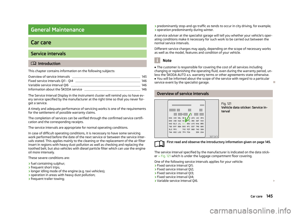
Fig. 121
Vehicle data sticker: Service in-
terval
First read and observe the introductory information given on page 145.
The service interval specified by the manufacturer is indicated on the data stick-
er » Fig. 121 which is under the luggage compartment floor covering.
One of the following service intervals applies for your vehicle: › Fixed service interval QI1;
› Fixed service interval QI2;
› Fixed service interval QI3;
› Fixed service interval QI4;
› Variable service interval QI6.
145Car care
Page 169 of 223

The oil level must be checked at regular intervals. We recommend it be checked
after each time you refuel or prior to making a long journey.
We recommend maintaining the oil level within the range A
, but not above , if
the engine has been operating at high loads, for example, during a lengthy motor-
way trip during the summer months, towing a trailer or negotiating a high moun- tain pass.
The warning light in the instrument cluster will indicate whether the oil level is too low » page 21 , Engine oil . Check the oil level using the dipstick as soon
as possible. Add oil accordingly.
CAUTION
■ Always check the oil level on vehicles with the 1.2 l/44 kW engine when the en-
gine is cold. Otherwise the measuring result is incorrect und oil could be incor-
rectly replenished - risk of engine damage!■
The oil level must never be above the
A
range » Fig. 127 – there is a risk of
damaging the exhaust system.
Note
Engine oil specifications » page 164.
Replenishing
First read and observe the introductory information and safety warn-
ings
on page 164.
›
Check the oil level » page 165.
›
Unscrew the cap of the engine oil filler opening.
›
Replenish the oil in portions of 0.5 litres in accordance with the correct specifi-
cations » page 164 .
›
Check the oil level » page 165.
›
Carefully screw on the oil filler opening cap and push the dipstick in fully.
Changing
First read and observe the introductory information and safety warn-ings
on page 164.
The engine oil must be changed at specified service intervals » page 145 or ac-
cording to the service interval display » page 16, Service Interval Display .
Coolant
Introduction
This chapter contains information on the following subjects:
Capacity
167
Checking the coolant level
167
Replenishing
168
The coolant consists of water with a concentration of coolant additive. This mix-
ture guarantees antifreeze protection, protects the cooling/heater system
against corrosion and prevents the formation of scale.
Vehicles exported to countries with a mild climate are already factory-filled with
a coolant which offers antifreeze protection down to about -25 ℃. In these coun-
tries the concentration of coolant additive should be at least 40 %.
Vehicles exported to countries with a cold climate are already factory-filled with a
coolant which offers antifreeze protection down to about -35 °C. In these coun-
tries the concentration of coolant additive should be at least 50 %.
If a higher concentration of antifreeze is required for climatic reasons, the amount
of coolant additive can only be increased up to a maximum of 60 % (antifreeze
protection down to approx. -40 °C).
When refilling, only use the same antifreeze identified on the coolant expansion vessel » Fig. 128 on page 167.
166General Maintenance
Page 171 of 223

If the coolant level in the coolant expansion tank is too low, this is indicated by
the warning light lighting up in the instrument cluster » page 22, Coolant .
We still recommend inspecting the coolant level directly at the reservoir from
time to time.
Loss of coolant
A loss of coolant is first and foremost an indication of a leak in the system. Do
not merely top up the coolant. Have the cooling system checked by a specialist
garage.
Replenishing
First read and observe the introductory information and safety warn-
ings
on page 166.
Only top up with new coolant.
›
Switch off the engine.
›
Allow the engine to cool.
›
Place a cloth over the cap of the coolant expansion tank and carefully unscrew
the cap.
›
Replenish the coolant.
›
Turn the cap until it clicks into place.
Do not use an alternative additive if the specified coolant is not available in an emergency. In this case, just use water and have the correct mixing ratio of waterand the coolant additive restored by a specialist garage as soon as possible.
Do not fill the coolant above the mark
A
(max.) » Fig. 128 on page 167. Excess
coolant heats up and then is forced out of the cooling system through the pres-
sure relief valve in the cap.
Brake fluid
Introduction
This chapter contains information on the following subjects:
Level check
168
Changing
169WARNING■ The engine compartment of your car is a hazardous area. While working in
the engine compartment, be sure to observe the following warn- ings » page 160 .■
Do not continue your journey if the fluid level has fallen below the MIN
marking » Fig. 129 on page 168 - there is a risk of an accident. Seek help from
a specialist garage.
■
Do not use used brake fluid - the function of the brake system may be im-
paired – there is the risk of an accident.
CAUTION
Brake fluid damages the paintwork of the vehicle.
Note
The brake fluid is changed as part of a prescribed inspection service.
Level check
Fig. 129
Engine compartment: Brake fluid
reservoir
First read and observe the introductory information and safety warn-
ings on page 168.
The brake fluid reservoir is located in the engine compartment.
›
Switch off the engine.
›
Open the bonnet.
›
Check the level of brake fluid in the reservoir » Fig. 129.
The level must be between the “MIN” and “MAX” markings.
168General Maintenance
Page 172 of 223

A slight drop in the fluid level results in operation due to normal wear and tear
and the automatic adjustment of the brake pads.
There may be an indication of a leak in the brake system, however, if the fluid lev-
el drops significantly within a short time or if it drops below the “MIN” marking.
If the brake fluid level is too low, this is indicated by the warning light lighting
up in the instrument cluster » page 20, Brake system .
Changing
First read and observe the introductory information and safety warn-ings
on page 168.
Brake fluid absorbs moisture. Over time it therefore absorbs moisture from the
environment.
Excessive water in the brake fluid may be the cause of corrosion in the brake sys-
tem.
The water content lowers the boiling point of the brake fluid.
The brake fluid must comply with the following standards or specifications: › VW 50114;
› FMVSS 116 DOT4.
Vehicle battery
Introduction
This chapter contains information on the following subjects:
Open cover
170
Checking the electrolyte level
171
Operation in winter
171
Charging
171
Disconnecting or reconnecting
172
Replacing
172
Automatic load deactivation
172Warning symbols on the vehicle batterySymbolMeaningAlways wear eye protection.Battery acid is severely caustic. Always wear gloves and eye protec- tion.Keep fire, sparks, open flames and lit cigarettes well clear of the ve-
hicle battery.When charging the vehicle battery, a highly explosive gas mixture is
produced.Keep children away from the vehicle battery.WARNINGThere is a risk of injuries, poisoning, chemical burns, explosions or fire when
carrying out any work on the battery and on the electrical system. It is essen-
tial to comply with the generally applicable rules of safety as well as the warn- ing instructions outlined below.■
Keep children away from the vehicle battery.
■
Do not tilt the battery otherwise battery electrolyte may flow out of the bat-
tery vent openings. Protect your eyes by wearing safety glasses or a face
shield – there is a risk of being blinded.
■
Always wear protective gloves, eye and skin protection when handling the
vehicle battery.
■
The battery acid is strongly corrosive and must, therefore, be handled with
the greatest of care.
■
Corrosive fumes in the air irritate the air passages and lead to conjunctivitis
and inflammation of the air passages in the lungs.
■
Battery acid corrodes dental enamel and creates deep wounds on contact
with the skin which take a long time to heal. Repeated contact with diluted
acids causes skin diseases (inflammations, ulcers, slin cracks).
■
If any battery electrolyte comes into contact with your eyes, rinse the eyes
immediately with clear water for several minutes - consult a doctor immedi-
ately.
■
Splashes of acid on your skin or clothes should be neutralised as soon as
possible using soap suds and then rinsed with plenty of water. Seek immedi-
ate medical assistance if you swallow battery acid.
169Inspecting and replenishing
Page 196 of 223

Fuses in the dash panelFig. 150
Underside of the dash panel:
Distribution board cover.
Fig. 151
Schematic representation of the fuse box for vehicles with left-
hand steering/right-hand steering
First read and observe the introductory information and safety warn-
ings
on page 192.
The fuses are located on the left side of the dash panel behind a cover.
› Carefully remove the cover in the direction of the arrow
» Fig. 150.
› After the fuse has been replaced, replace the cover in the dash panel in the op-
posite direction of the arrow so that the guide lugs are guided into the open- ings of the dash panel. Close the cover until it clicks into place.
Fuse assignment in the dash panel
No.Power consumer1S-contact2START-STOP, air-conditioning system3Instrument cluster, headlamp beam adjustmentNo.Power consumer4Control unit for ABS, button for START STOP5Petrol engine: Speed regulating system6Reversing light (manual gearbox)7Ignition, engine control unit, automatic gearbox8Brake pedal switch, clutch pedal switch9Operating controls for the heating, control unit for air conditioning sys-
tem, parking aid, control unit for cornering lights, radiator fan, washing nozzles10Windscreen Wiper and Washer System11Mirror adjustment12Control unit for trailer detection13Automatic gearbox control unit14Motor for halogen projector headlights with cornering light function15PDA navigation system16Electrohydraulic power steering17Light switch power supply18Mirror heater19S-contact20Alarm21Reversing light, fog lights with the function CORNER22Operating controls for the heating, control unit for air conditioning sys-
tem, parking aid, mobile phone, instrument cluster, steering angle
sender, ESC, vehicle voltage control unit, multifunction steering wheel23Interior lighting, storage compartment and luggage compartment, side
lights24Central control unit25Seat heaters26Rear window wiper27Telephone preinstallation28Petrol engine: AKF valve, Diesel engine: Control flap29Injection, coolant pump30Fuel pump, ignition, Cruise control system, operation of PTC relay31Lambda probe 193Fuses and light bulbs
Page 197 of 223

No.Power consumer32High pressure fuel pump, pressure valve33Engine control unit34Engine control unit, vacuum pump35Daytime running lights/radio for vehicles with START-STOP36Main beam37Rear fog light, DC/DC converter START-STOP38Fog lights39Air blower for heating40-41Not assigned42Rear window heater43Horn44Windscreen wipers45Central control unit for convenience system46Engine control unit, fuel pump47Cigarette lighter, power socket in the luggage compartment48ABS, START-STOP (DC/DC) converter ESP49Turn signal lights, brake lights50START-STOP (DC/DC) transformer, radio51Electrical power window (front and rear) - left side52Electrical power window (front and rear) - right side53Parking light = left side, electrical sliding/tilting roof54START-STOP (instrument cluster), alarm55Automatic gearbox control unit56Headlight cleaning system, parking light - right side57Left low beam, headlight range adjustment58Low beam on the right
Fuses in the engine compartmentFig. 152
Vehicle battery: Distribution board cover.
Fig. 153
Schematic representation of
fuse box in engine compartment
First read and observe the introductory information and safety warn-
ings on page 192.
› Press the securing clips on the fuse box cover together at the same time in the
direction of arrow
A
» Fig. 152 and remove the cover in the direction of arrow
B
.
› Release the fixtures in the openings
C
using a flat screwdriver and fold the
cover upwards in direction of arrow
D
.
Fuse assignment in engine compartment
No.Power consumer1Alternator2Not assigned3Interior4Electrical auxiliary heating system 194Do-it-yourself