2013 RENAULT SCENIC sensor
[x] Cancel search: sensorPage 58 of 115
37B-58
MR-372-J84-37B000$504.mif
V11
ELECTRONIC PARKING BRAKE
Fault finding – Interpretation of faults
FPA
Vdiag No.: 0C, 04, 08,
0D, 11
37B
DF050
PRESENT
OR
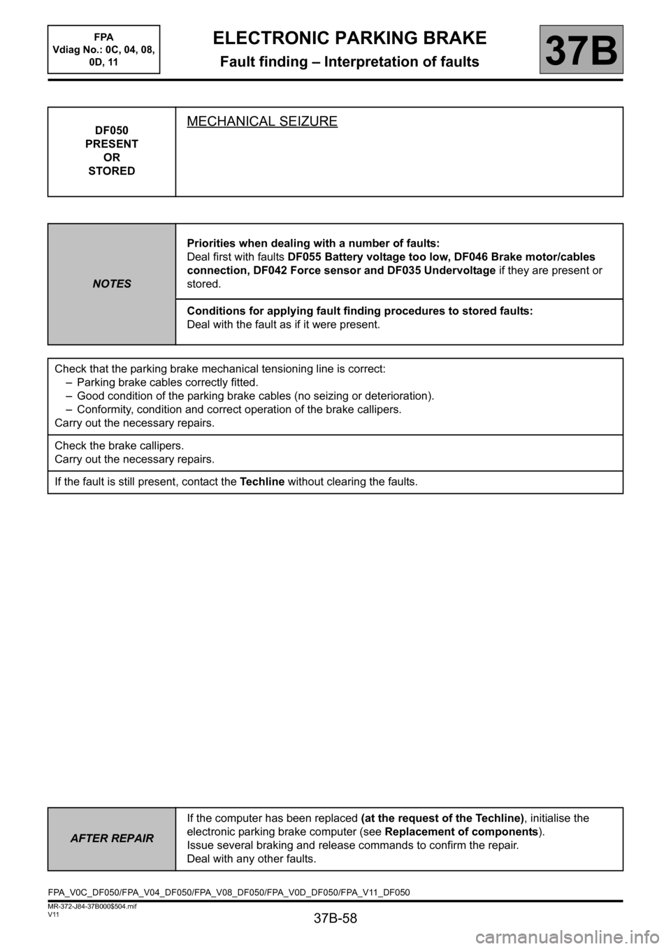
STOREDMECHANICAL SEIZURE
NOTESPriorities when dealing with a number of faults:
Deal first with faults DF055 Battery voltage too low, DF046 Brake motor/cables
connection, DF042 Force sensor and DF035 Undervoltage if they are present or
stored.
Conditions for applying fault finding procedures to stored faults:
Deal with the fault as if it were present.
Check that the parking brake mechanical tensioning line is correct:
– Parking brake cables correctly fitted.
– Good condition of the parking brake cables (no seizing or deterioration).
– Conformity, condition and correct operation of the brake callipers.
Carry out the necessary repairs.
Check the brake callipers.
Carry out the necessary repairs.
If the fault is still present, contact the Techline without clearing the faults.
AFTER REPAIRIf the computer has been replaced (at the request of the Techline), initialise the
electronic parking brake computer (see Replacement of components).
Issue several braking and release commands to confirm the repair.
Deal with any other faults.
FPA_V0C_DF050/FPA_V04_DF050/FPA_V08_DF050/FPA_V0D_DF050/FPA_V11_DF050
Page 63 of 115
37B-63
MR-372-J84-37B000$504.mif
V11
ELECTRONIC PARKING BRAKE
Fault finding – Interpretation of faults
FPA
Vdiag No.: 0C, 04, 08,
0D, 11
37B
DF055
PRESENT
OR
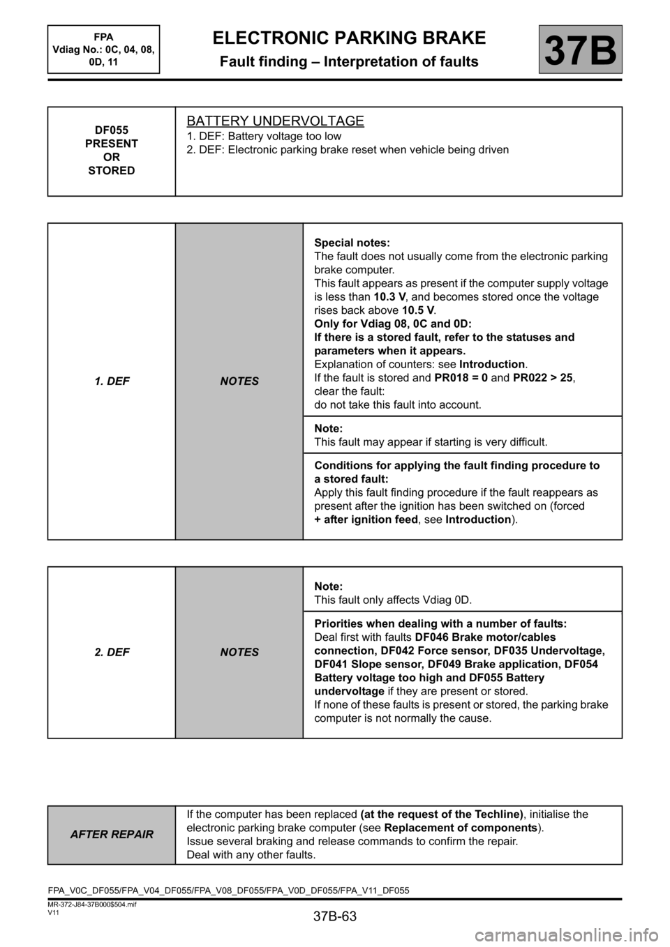
STOREDBATTERY UNDERVOLTAGE
1. DEF: Battery voltage too low
2. DEF: Electronic parking brake reset when vehicle being driven
1. DEF
NOTESSpecial notes:
The fault does not usually come from the electronic parking
brake computer.
This fault appears as present if the computer supply voltage
is less than 10.3 V, and becomes stored once the voltage
rises back above 10.5 V.
Only for Vdiag 08, 0C and 0D:
If there is a stored fault, refer to the statuses and
parameters when it appears.
Explanation of counters: see Introduction.
If the fault is stored and PR018 = 0 and PR022 > 25,
clear the fault:
do not take this fault into account.
Note:
This fault may appear if starting is very difficult.
Conditions for applying the fault finding procedure to
a stored fault:
Apply this fault finding procedure if the fault reappears as
present after the ignition has been switched on (forced
+ after ignition feed, see Introduction).
2. DEF
NOTESNote:
This fault only affects Vdiag 0D.
Priorities when dealing with a number of faults:
Deal first with faults DF046 Brake motor/cables
connection, DF042 Force sensor, DF035 Undervoltage,
DF041 Slope sensor, DF049 Brake application, DF054
Battery voltage too high and DF055 Battery
undervoltage if they are present or stored.
If none of these faults is present or stored, the parking brake
computer is not normally the cause.
AFTER REPAIRIf the computer has been replaced (at the request of the Techline), initialise the
electronic parking brake computer (see Replacement of components).
Issue several braking and release commands to confirm the repair.
Deal with any other faults.
FPA_V0C_DF055/FPA_V04_DF055/FPA_V08_DF055/FPA_V0D_DF055/FPA_V11_DF055
Page 66 of 115
37B-66
MR-372-J84-37B000$504.mif
V11
ELECTRONIC PARKING BRAKE
Fault finding – Interpretation of faults
FPA
Vdiag No.: 0C, 04, 08,
0D, 11
37B
DF057
PRESENT
OR
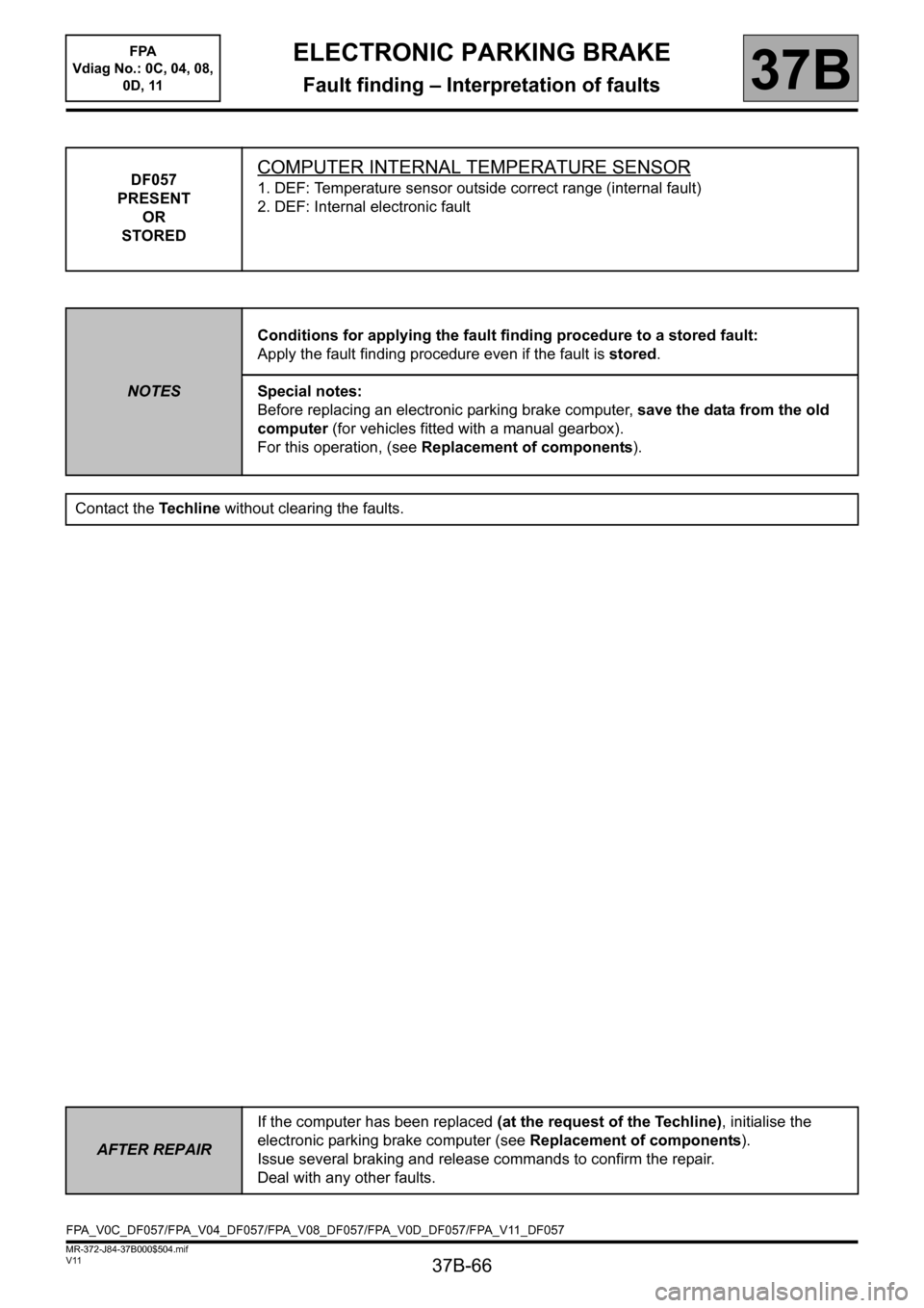
STOREDCOMPUTER INTERNAL TEMPERATURE SENSOR
1. DEF: Temperature sensor outside correct range (internal fault)
2. DEF: Internal electronic fault
NOTESConditions for applying the fault finding procedure to a stored fault:
Apply the fault finding procedure even if the fault is stored.
Special notes:
Before replacing an electronic parking brake computer, save the data from the old
computer (for vehicles fitted with a manual gearbox).
For this operation, (see Replacement of components).
Contact the Techline without clearing the faults.
AFTER REPAIRIf the computer has been replaced (at the request of the Techline), initialise the
electronic parking brake computer (see Replacement of components).
Issue several braking and release commands to confirm the repair.
Deal with any other faults.
FPA_V0C_DF057/FPA_V04_DF057/FPA_V08_DF057/FPA_V0D_DF057/FPA_V11_DF057
Page 84 of 115
37B-84
MR-372-J84-37B000$576.mif
V11
FPA
Vdiag No.: 0C, 04, 08,
0D, 11ELECTRONIC PARKING BRAKE
Fault finding – Conformity check37B
SUB-FUNCTION: AUTOMATIC RELEASE (CONTINUED 3)
NOTESOnly carry out this conformity check after carrying out a complete check using the
diagnostic tool.
Application conditions: ignition on (forced + after ignition, see Introduction)
Note:
The interpretation of these statuses and parameters is only valid with the
ignition switched on, the statuses and parameters displayed in blue on the
diagnostic tool is information supplied by other computers, which are transmitted via
the multiplex network. If these variables display inconsistent values, check that the
multiplex system test has not shown up any faulty connections. Repair the faulty
multiplex connections before looking for a possible problem with the signals.
Each sub-function in this test is associated with a Fault finding chart.
Special notes:
The diagnostic tool may display the message Computer busy when displaying
statuses and parameters. This message is displayed when the parking brake is
applying or releasing the brake, because the computer gives priority to controlling the
motor before transmitting variables. If this message is displayed, exit the current
screen and then return to it.
Order FunctionParameter or Status
Checked or ActionDisplay and notes Fault finding
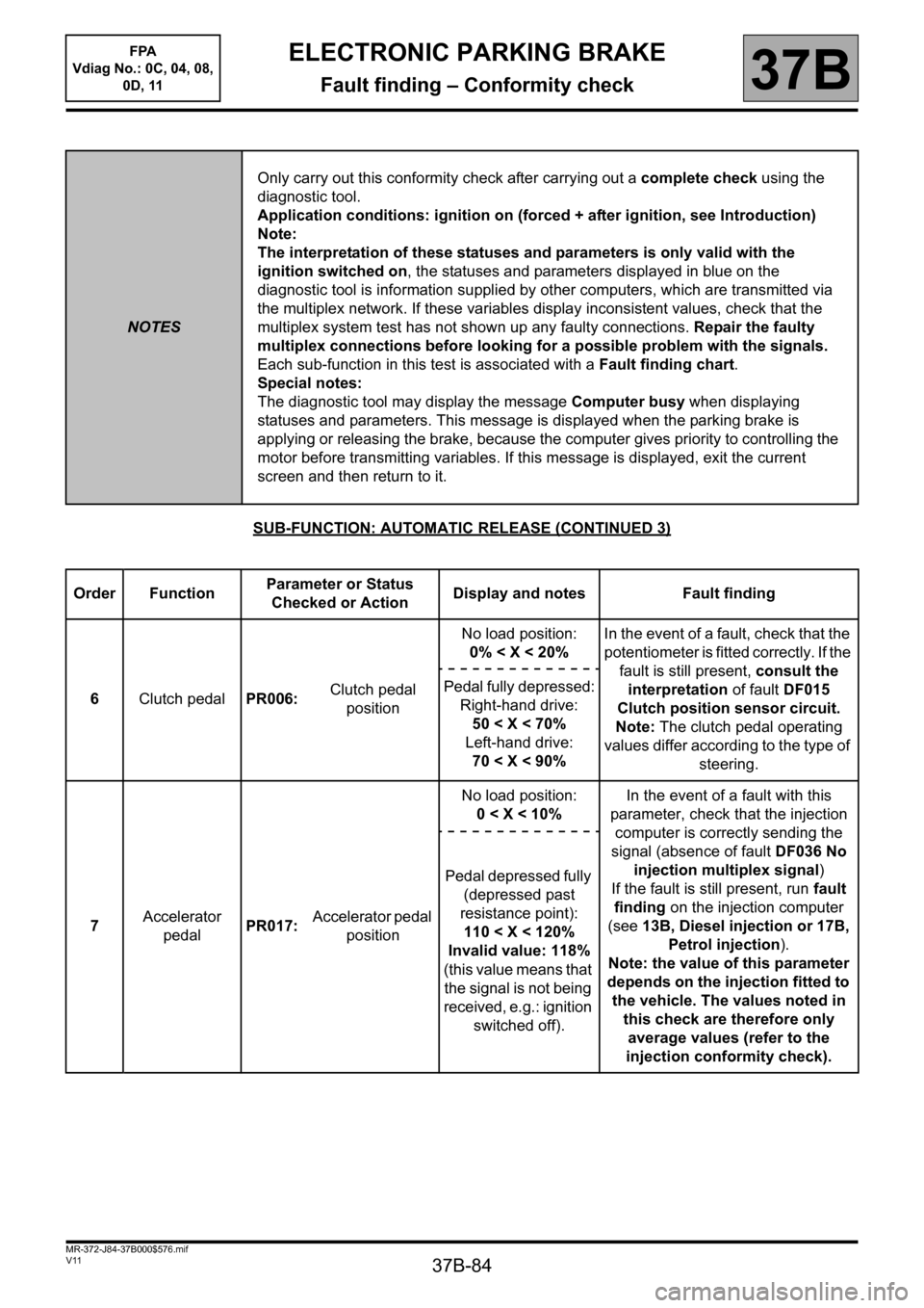
6Clutch pedalPR006: Clutch pedal
positionNo load position:
0% < X < 20%In the event of a fault, check that the
potentiometer is fitted correctly. If the
fault is still present, consult the
interpretation of fault DF015
Clutch position sensor circuit.
Note: The clutch pedal operating
values differ according to the type of
steering. Pedal fully depressed:
Right-hand drive:
50 < X < 70%
Left-hand drive:
70 < X < 90%
7 Accelerator
pedalPR017: Accelerator pedal
positionNo load position:
0
computer is correctly sending the
signal (absence of fault DF036 No
injection multiplex signal)
If the fault is still present, run fault
finding on the injection computer
(see 13B, Diesel injection or 17B,
Petrol injection).
Note: the value of this parameter
depends on the injection fitted to
the vehicle. The values noted in
this check are therefore only
average values (refer to the
injection conformity check). Pedal depressed fully
(depressed past
resistance point):
110 < X < 120%
Invalid value: 118%
(this value means that
the signal is not being
received, e.g.: ignition
switched off).
Page 102 of 115

37B-102
MR-372-J84-37B000$792.mif
V11
ELECTRONIC PARKING BRAKE
Fault finding – Interpretation of commands
FPA
Vdiag No.: 0C, 04, 08,
0D, 11
37B
SC006
ENTER CLUTCH PEDAL PROGRAMMING
NOTESSpecial notes:
The commands are found in the tool's repair mode, Programming button.
Once the electronic parking brake computer has been changed.
Run command SC006 Enter clutch pedal programming after running command SC005 Backup clutch pedal
programming.
Test braking and release, and starting the electronic parking brake computer when applied, to check conformity.
Park the vehicle on a level surface.
– Select the diagnostic tool's Repair mode menu.
– From the tool's navigation menu, select Programming.
– Run command SC006 Enter clutch pedal programming.
Note:
When a new electronic parking brake computer is initialised, the angle sensor is calibrated after running
command VP011 Computer calibration and initialisation.
AFTER REPAIRRepeat the conformity check from the start.
Page 103 of 115

37B-103
MR-372-J84-37B000$792.mif
V11
ELECTRONIC PARKING BRAKE
Fault finding – Interpretation of commands
FPA
Vdiag No.: 0C, 04, 08,
0D, 11
37B
SC008
SLOPE INITIALISATION
NOTESSpecial notes:
The commands are found in the tool's repair mode, Programming button.
Using the diagnostic tool's automatic release sub-function screen, display parameter PR003 Slope value.
If the value displayed is not 0d° ± 2 on level ground: run the command by following the procedure described
below.
Park the vehicle on a level surface.
– Select the diagnostic tool's Repair mode menu.
– From the tool's navigation menu, select Programming.
– Run command SC008 "Slope initialisation".
– Check the conformity of parameter PR003 Slope value.
Note:
When a new electronic parking brake computer is initialised, the angle sensor is calibrated after running
command VP011 Computer calibration and initialisation.
AFTER REPAIRRepeat the conformity check from the start.
Page 105 of 115
37B-105
MR-372-J84-37B000$936.mif
V11
ELECTRONIC PARKING BRAKE
Fault finding – Fault finding chart
FPA
Vdiag No.: 0C, 04, 08,
0D, 11
37B
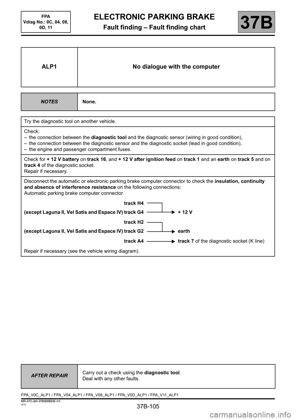
ALP1 No dialogue with the computer
NOTESNone.
Try the diagnostic tool on another vehicle.
Check:
– the connection between the diagnostic tool and the diagnostic sensor (wiring in good condition),
– the connection between the diagnostic sensor and the diagnostic socket (lead in good condition),
– the engine and passenger compartment fuses.
Check for + 12 V battery on track 16, and + 12 V after ignition feed on track 1 and an earth on track 5 and on
track 4 of the diagnostic socket.
Repair if necessary.
Disconnect the automatic or electronic parking brake computer connector to check the insulation, continuity
and absence of interference resistance on the following connections:
Automatic parking brake computer connector
track H4
(except Laguna II, Vel Satis and Espace IV) track G4 + 12 V
track H2
(except Laguna II, Vel Satis and Espace IV) track G2 earth
track A4 track 7 of the diagnostic socket (K line)
Repair if necessary (see the vehicle wiring diagram).
AFTER REPAIRCarry out a check using the diagnostic tool.
Deal with any other faults.
FPA_V0C_ALP1 / FPA_V04_ALP1 / FPA_V08_ALP1 / FPA_V0D_ALP1 / FPA_V11_ALP1
ELECTRONIC PARKING BRAKE
Fault finding – Fault finding chart
MR-372-J84-37B000$936.mif
Page 107 of 115
37B-107
MR-372-J84-37B000$936.mif
V11
ELECTRONIC PARKING BRAKE
Fault finding – Fault finding chart
FPA
Vdiag No.: 0C, 04, 08,
0D, 11
37B
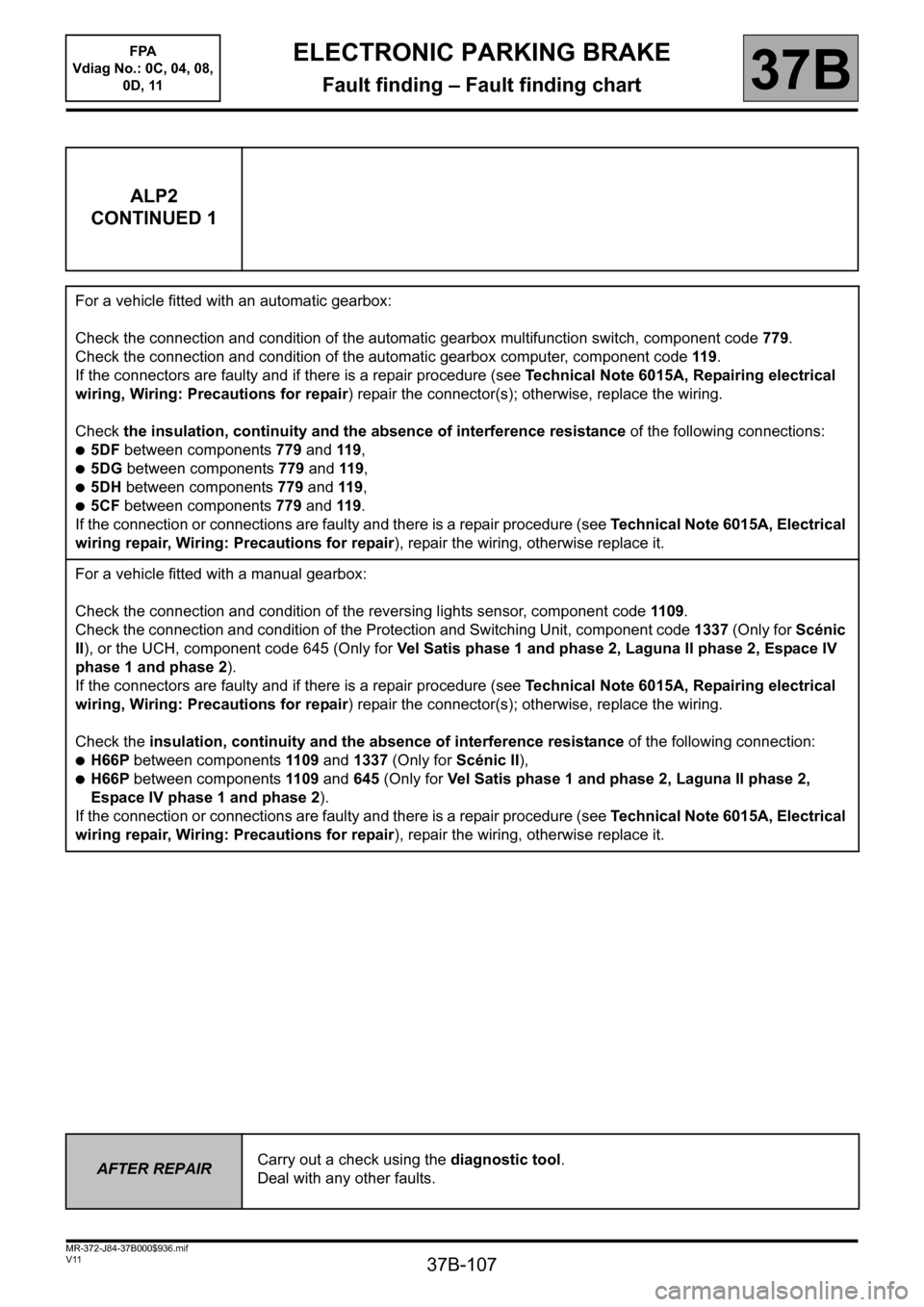
ALP2
CONTINUED 1
For a vehicle fitted with an automatic gearbox:
Check the connection and condition of the automatic gearbox multifunction switch, component code 779.
Check the connection and condition of the automatic gearbox computer, component code 119.
If the connectors are faulty and if there is a repair procedure (see Technical Note 6015A, Repairing electrical
wiring, Wiring: Precautions for repair) repair the connector(s); otherwise, replace the wiring.
Check the insulation, continuity and the absence of interference resistance of the following connections:
●5DF between components 779 and 119,
●5DG between components 779 and 119,
●5DH between components 779 and 119,
●5CF between components 779 and 119.
If the connection or connections are faulty and there is a repair procedure (see Technical Note 6015A, Electrical
wiring repair, Wiring: Precautions for repair), repair the wiring, otherwise replace it.
For a vehicle fitted with a manual gearbox:
Check the connection and condition of the reversing lights sensor, component code 1109.
Check the connection and condition of the Protection and Switching Unit, component code 1337 (Only for Scénic
II), or the UCH, component code 645 (Only for Vel Satis phase 1 and phase 2, Laguna II phase 2, Espace IV
phase 1 and phase 2).
If the connectors are faulty and if there is a repair procedure (see Technical Note 6015A, Repairing electrical
wiring, Wiring: Precautions for repair) repair the connector(s); otherwise, replace the wiring.
Check the insulation, continuity and the absence of interference resistance of the following connection:
●H66P between components 1109 and 1337 (Only for Scénic II),
●H66P between components 1109 and 645 (Only for Vel Satis phase 1 and phase 2, Laguna II phase 2,
Espace IV phase 1 and phase 2).
If the connection or connections are faulty and there is a repair procedure (see Technical Note 6015A, Electrical
wiring repair, Wiring: Precautions for repair), repair the wiring, otherwise replace it.
AFTER REPAIRCarry out a check using the diagnostic tool.
Deal with any other faults.