Page 66 of 115

37B-66
MR-372-J84-37B000$504.mif
V11
ELECTRONIC PARKING BRAKE
Fault finding – Interpretation of faults
FPA
Vdiag No.: 0C, 04, 08,
0D, 11
37B
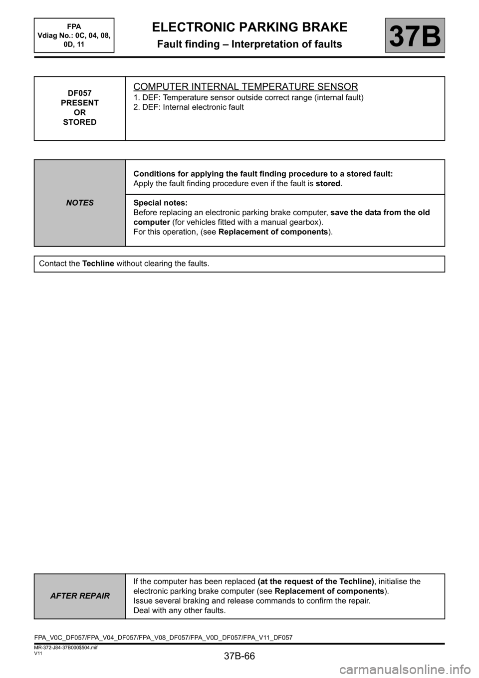
DF057
PRESENT
OR
STOREDCOMPUTER INTERNAL TEMPERATURE SENSOR
1. DEF: Temperature sensor outside correct range (internal fault)
2. DEF: Internal electronic fault
NOTESConditions for applying the fault finding procedure to a stored fault:
Apply the fault finding procedure even if the fault is stored.
Special notes:
Before replacing an electronic parking brake computer, save the data from the old
computer (for vehicles fitted with a manual gearbox).
For this operation, (see Replacement of components).
Contact the Techline without clearing the faults.
AFTER REPAIRIf the computer has been replaced (at the request of the Techline), initialise the
electronic parking brake computer (see Replacement of components).
Issue several braking and release commands to confirm the repair.
Deal with any other faults.
FPA_V0C_DF057/FPA_V04_DF057/FPA_V08_DF057/FPA_V0D_DF057/FPA_V11_DF057
Page 107 of 115

37B-107
MR-372-J84-37B000$936.mif
V11
ELECTRONIC PARKING BRAKE
Fault finding – Fault finding chart
FPA
Vdiag No.: 0C, 04, 08,
0D, 11
37B
ALP2
CONTINUED 1
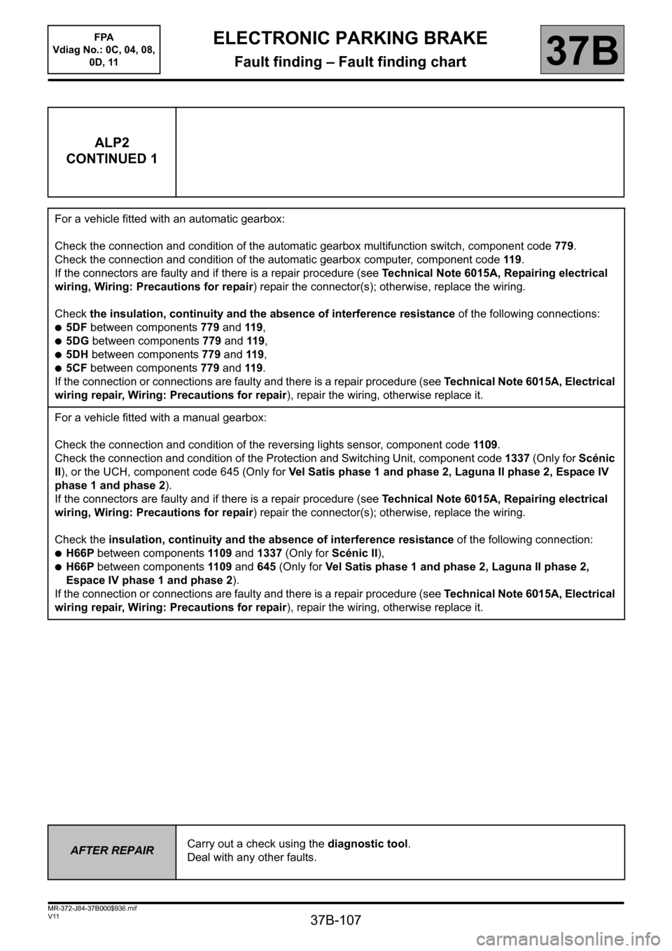
For a vehicle fitted with an automatic gearbox:
Check the connection and condition of the automatic gearbox multifunction switch, component code 779.
Check the connection and condition of the automatic gearbox computer, component code 119.
If the connectors are faulty and if there is a repair procedure (see Technical Note 6015A, Repairing electrical
wiring, Wiring: Precautions for repair) repair the connector(s); otherwise, replace the wiring.
Check the insulation, continuity and the absence of interference resistance of the following connections:
●5DF between components 779 and 119,
●5DG between components 779 and 119,
●5DH between components 779 and 119,
●5CF between components 779 and 119.
If the connection or connections are faulty and there is a repair procedure (see Technical Note 6015A, Electrical
wiring repair, Wiring: Precautions for repair), repair the wiring, otherwise replace it.
For a vehicle fitted with a manual gearbox:
Check the connection and condition of the reversing lights sensor, component code 1109.
Check the connection and condition of the Protection and Switching Unit, component code 1337 (Only for Scénic
II), or the UCH, component code 645 (Only for Vel Satis phase 1 and phase 2, Laguna II phase 2, Espace IV
phase 1 and phase 2).
If the connectors are faulty and if there is a repair procedure (see Technical Note 6015A, Repairing electrical
wiring, Wiring: Precautions for repair) repair the connector(s); otherwise, replace the wiring.
Check the insulation, continuity and the absence of interference resistance of the following connection:
●H66P between components 1109 and 1337 (Only for Scénic II),
●H66P between components 1109 and 645 (Only for Vel Satis phase 1 and phase 2, Laguna II phase 2,
Espace IV phase 1 and phase 2).
If the connection or connections are faulty and there is a repair procedure (see Technical Note 6015A, Electrical
wiring repair, Wiring: Precautions for repair), repair the wiring, otherwise replace it.
AFTER REPAIRCarry out a check using the diagnostic tool.
Deal with any other faults.
Page 110 of 115

37B-110
MR-372-J84-37B000$936.mif
V11
ELECTRONIC PARKING BRAKE
Fault finding – Fault finding chart
FPA
Vdiag No.: 0C, 04, 08,
0D, 11
37B
ALP3
CONTINUED
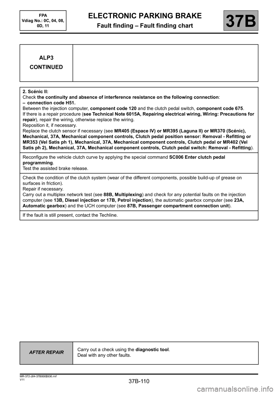
2. Scénic II:
Check the continuity and absence of interference resistance on the following connection:
– connection code H51.
Between the injection computer, component code 120 and the clutch pedal switch, component code 675.
If there is a repair procedure (see Technical Note 6015A, Repairing electrical wiring, Wiring: Precautions for
repair), repair the wiring, otherwise replace the wiring.
Reposition it, if necessary.
Replace the clutch sensor if necessary (see MR405 (Espace IV) or MR395 (Laguna II) or MR370 (Scénic),
Mechanical, 37A, Mechanical component controls, Clutch pedal position sensor: Removal - Refitting or
MR353 (Vel Satis ph 1), Mechanical, 37A, Mechanical component controls, Clutch pedal or MR402 (Vel
Satis ph 2), Mechanical, 37A, Mechanical component controls, Clutch pedal switch: Removal - Refitting).
Reconfigure the vehicle clutch curve by applying the special command SC006 Enter clutch pedal
programming.
Test the assisted brake release.
Check the condition of the clutch system (wear of the different components, possible build-up of grease on
surfaces in friction).
Repair if necessary.
Carry out a multiplex network test (see 88B, Multiplexing) and check for any potential faults on the injection
computer (see 13B, Diesel injection or 17B, Petrol injection), the automatic gearbox computer (see 23A,
Automatic gearbox) and the UCH computer (see 87B, Passenger compartment connection unit).
If the fault is still present, contact the Techline.
AFTER REPAIRCarry out a check using the diagnostic tool.
Deal with any other faults.