2013 RENAULT KANGOO rail pressure sensor
[x] Cancel search: rail pressure sensorPage 10 of 204

13B-10V1 MR-376-X76-13B000$030.mif
13B
DCM 1.2 Injection
Program no.: 4C
Vdiag No.: 08
System outline
The DCM 1.2 injection system used on the K9K engine is an electronically-managed high pressure injection system.
The fuel is compressed by a high pressure pump then stored in a rail that feeds the injectors. Injection takes place
when a current pulse is applied to the injector holders.
The amount injected is proportional to the rail pressure and the applied pulse length, and the start of injection is
synchronised with the start of the pulse.
The system includes two subsystems, which have different fuel pressure levels:
– the low pressure circuit contains the tank, the diesel fuel filter, the transfer pump and the injector holder return pipes,
– the high pressure circuit contains the high pressure pump, the rail, the injector holders and the high pressure pipes.
The injection system contains a number of sensors and actuators for controlling and monitoring the entire system.
Functions provided
Function: Fuel supply management (timing, flow and pressure).
Quantity of fuel injected and injection timing setting
The injection checking parameters are the quantities to be injected and their respective timing.
These are calculated by the computer using signals from the following sensors:
– Engine speed (Crankshaft +Cam for synchronisation).
– Accelerator pedal.
– Turbocharging pressure and air temperature (Turbocharger pressure).
– Coolant temperature.
– Air temperature.
– Air charge (Flow and Pressure).
– Pressure in the rail.
The quantities to be injected and their respective timing are converted into:
– a reference tooth,
– the time between this tooth and the start of the pulse,
– the time for which the supply to the injector holder is on.
Each injector holder is controlled by an electrical current which is sent according to previously calculated data. The
system makes one or two injections (one pilot injection, one main injection).
The general principle is to calculate an overall injected flow, which is then divided into the main injection flow and a
pilot injection flow to promote correct combustion and help reduce pollutant emissions.
DIESEL INJECTION
Fault finding – System operation
Page 11 of 204

13B-11V1 MR-376-X76-13B000$030.mif
DIESEL INJECTION
Fault finding – System operation13B
DCM 1.2 Injection
Program no.: 4C
Vdiag No.: 08
An accelerometer is used to monitor some of the fuel injection deviation. This has several roles:
– Protecting the engine by detecting injection leaks (disabled on the basic version).
– Checking the pilot quantity by measuring deviation and dispersion.
By changing both the injection duration and advance, the quantity of fuel injected and the mixture's moment of
ignition can be readjusted.
Rail pressure check
The quality of combustion is influenced by the size of the atomised droplets in the cylinder.
In the combustion chamber, smaller fuel droplets will have time to burn fully, and will not produce smoke or
unburned particles. To meet emission control requirements, the droplet size, and therefore the size of the injection
holes, must be reduced.
With smaller holes, less fuel will be able to be introduced at a given pressure, which limits the power. To offset this
disadvantage, the quantity of fuel injected must be increased, which means increased pressure (and more holes in
the injector nozzles).
For the DCM 1.2 injection system, the pressure reaches 1400 bar - 1600 bar in the rail and must be constantly
regulated. The measuring circuit comprises an active pressure sensor on the rail connected to an analogue port on
the computer.
The high pressure pump is supplied at low pressure (5bar) by a built-in transfer pump. This pump supplies the rail.
The rail filling pressure is controlled by the fuel flow actuator (IMV) and the discharge pressure is controlled by the
injector valves. This compensates for pressure drops. The flow actuator enables the high pressure pump to supply
the exact quantity of diesel fuel required to maintain the rail pressure. This mechanism minimises the heat generated
and improves engine output.
In order to discharge the rail using the injector valves, the valves are actuated by short electrical pulses which are:
– short enough in amplitude not to open the injector (and pass through the return circuit from the injectors),
– long enough in time to open the valves and discharge the rail.
The fuel surplus is sent back to the fuel filter or the tank, according to its flow. If there is no fuel flow actuator control,
the rail pressure is limited by a discharge valve fitted on the pump.
New pump chamber filling procedure (pump boosting)
The pump lubrication goes through a booster cycle during which the pump is filled and pressurised before
"transferring" the diesel fuel to the rail.
This lubrication goes through programming called "filling the new pump chamber", which prohibits starting for
approximately 10 seconds (the time required to fill the pump and to start if the key is released before the end of this
"first starting" phase). Power latch is not necessary before attempting to start the vehicle again.
This procedure runs when a computer is replaced if the parameters relating to the rail pressure have not been
copied into the new computer, or otherwise, after reprogramming of the injection computer.
Page 12 of 204
13B-12V1 MR-376-X76-13B000$030.mif
DIESEL INJECTION
Fault finding – System operation13B
DCM 1.2 Injection
Program no.: 4C
Vdiag No.: 08
Idling speed regulation
The computer handles the calculation of idling speed. This has to take account of the instantaneous power level to
be supplied, according to the following factors:
– engine coolant temperature,
– gear ratio engaged,
– battery charge,
– electrical consumers (Additional heating, Air conditioning, Fan Unit, electric windows, etc.) active or inactive,
– system faults detected.
Individual injector correction (C2I)
The DCM 1.2 system injectors must be calibrated with correction values so that their flow may be adjusted precisely.
Each injector is calibrated for different pressures on a test bench, and its specifications are shown on a label
attached to the body of the injector holders. These individual correction values are then entered into the computer
EEPROM, which can then control the injectors, taking their manufacturing variations into account.
Measuring the angular position (Cylinder reference sensor)
The angular position is measured using a magneto-inductive sensor triggered by machined teeth on the shaft
flywheel. This flywheel has sixty teeth separated by six degrees minus two missing teeth, that form a notch.
A second sensor (Hall effect) triggered by a machined tooth on the high pressure pump drive pulley (synchronised
with the camshaft), which rotates at half the engine speed, supplies an injection cycle running signal. By comparing
the signals from these two sensors, the computer's APS module (Angular Position Subsystem) is able to supply the
synchronisation components to the system assembly, namely:
– the angular position of the flywheel
– the speed and number of the active injector
– the injection cycle progress.
This module also supplies the system with the engine speed signal.
Flow capacity function (VLC)
Because of the combination of several parameters such as the diesel fuel temperature, part wear, clogging of the
diesel filter etc., the system limit may be reached during its service life. If this happens, the rail pressure cannot be
maintained because the pump lacks the necessary capacity. If the pump lacks the necessary capacity, this
programming will therefore reduce the requested flow to a value that will enable the pressure monitoring system to
control the pressure again.
The customer may have noticed a loss of vehicle performance when this program is activated (confirmed by status
Flow capacity function). This is part of normal operation.
Page 22 of 204

13B-22V1 MR-376-X76-13B000$060.mif
13B
DCM 1.2 Injection
Program no.: 4C
Vdiag No.: 08
Tool fault Associated DTC Diagnostic tool name
DF001 0115Coolant temperature sensor circuit
DF002 0070Air temperature sensor circuit
DF003 2226Atmospheric pressure sensor circuit
DF005 0335Engine speed sensor circuit
DF007 0190Rail pressure sensor circuit
DF008 0225Pedal potentiometer circuit gang 1
DF009 2120Pedal potentiometer circuit gang 2
DF010 0409EGR position sensor circuit
DF014 0500Vehicle speed information circuit
DF015 0685Main relay control circuit
DF016 0403EGR control circuit
DF017 0382Preheating unit control circuit
DF018 0480Low-speed fan unit control circuit
DF019 0481High-speed fan unit control circuit
DF021 0381Preheating warning light circuit
DF022 0650OBD warning light circuit
DF024 0231Low pressure actuator control circuit
DF025 0380Preheater unit diagnostic connection
DF026 0201Cylinder 1 injector circuit control
DF027 0202Cylinder 2 injector circuit control
DF028 0203Cylinder 3 injector circuit control
DF029 0204Cylinder 4 injector circuit control
DF032 1641Thermoplunger 1 relay control circuit
DF033 1642Thermoplunger 2 relay control circuit
DF034 1643Thermoplunger 3 relay control circuit
DF037 0513Immobiliser
DF038 0606Computer
DF039 0110Inlet air temperature sensor circuit
DF047 0560Computer feed voltage
DF049 0530Refrigerant sensor circuit
DF050 0571Brake switch circuit
DIESEL INJECTION
Fault finding – Fault summary table
Page 23 of 204
13B-23V1 MR-376-X76-13B000$060.mif
DIESEL INJECTION
Fault finding – Fault summary table13B
DCM 1.2 Injection
Program no.: 4C
Vdiag No.: 08
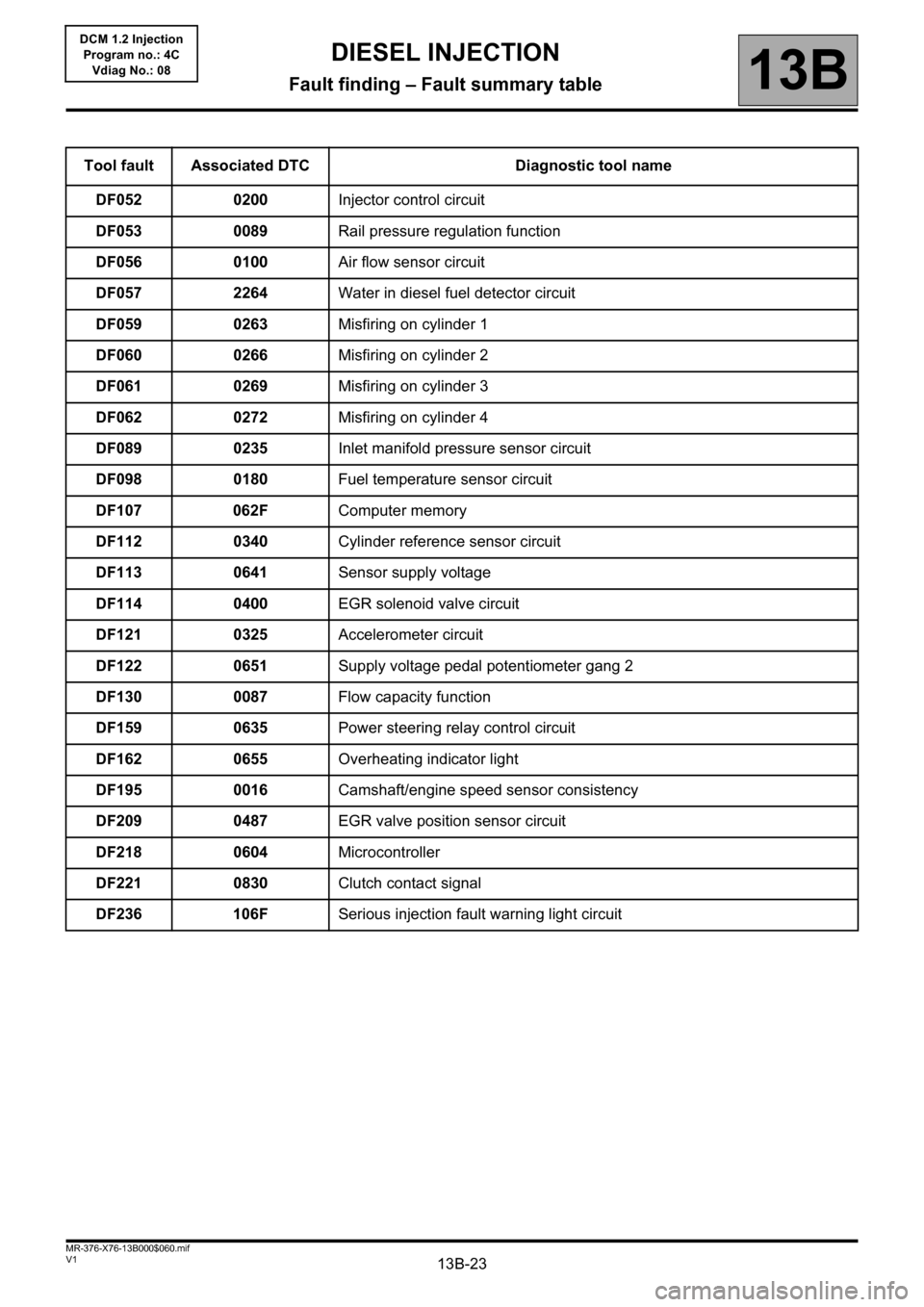
Tool fault Associated DTC Diagnostic tool name
DF052 0200Injector control circuit
DF053 0089Rail pressure regulation function
DF056 0100Air flow sensor circuit
DF057 2264Water in diesel fuel detector circuit
DF059 0263Misfiring on cylinder 1
DF060 0266Misfiring on cylinder 2
DF061 0269Misfiring on cylinder 3
DF062 0272Misfiring on cylinder 4
DF089 0235Inlet manifold pressure sensor circuit
DF098 0180Fuel temperature sensor circuit
DF107 062FComputer memory
DF112 0340Cylinder reference sensor circuit
DF113 0641Sensor supply voltage
DF114 0400EGR solenoid valve circuit
DF121 0325Accelerometer circuit
DF122 0651Supply voltage pedal potentiometer gang 2
DF130 0087Flow capacity function
DF159 0635Power steering relay control circuit
DF162 0655Overheating indicator light
DF195 0016Camshaft/engine speed sensor consistency
DF209 0487EGR valve position sensor circuit
DF218 0604Microcontroller
DF221 0830Clutch contact signal
DF236 106FSerious injection fault warning light circuit
Page 30 of 204

13B-30
AFTER REPAIRDeal with any faults declared by the diagnostic tool.
Clear the computer memory.
Carry out a road test followed by another check with the diagnostic tool.
V1 MR-376-X76-13B000$071.mif
DIESEL INJECTION
Fault finding – Interpretation of faults13B
DCM 1.2 Injection
Program no.: 4C
Vdiag No.: 08
DF007
PRESENT
OR
STOREDRAIL PRESSURE SENSOR CIRCUITCC.0: Short circuit to earth
CO.1: Open circuit or short circuit to +12 V
1.DEF: Inconsistency
2.DEF: Below minimum threshold
3.DEF: Above maximum threshold
4.DEF: Value outside permitted tolerance
NOTESPriority when dealing with a number of faults:
– DF113 Sensor supply voltage.
Conditions for applying the fault finding procedure to a stored fault:
The fault is declared present after the engine starts.
Special notes:
If fault DF007 is present, the engine stops and restarting is impossible.
Level 2 warning light comes on.
Use the Wiring Diagrams Technical Note for Logan, Sandero, Duster, Thalia 2/
Symbol 2 or Kangoo VLL.
Check the connection and condition of the rail pressure sensor connector, component code 1032.
Check the connection and condition of the injection computer connector, component code 120.
If the connectors are faulty and if there is a repair procedure (see Technical Note 6015A (Renault) or Technical
Note 9804A (Dacia), Electrical wiring repair, Wiring: Precautions for repair), repair the connector, otherwise
replace the wiring.
Check for + 5 V on connection 3LX of the rail pressure sensor, component code 1032.
Check for earth on connection 3LZ of the rail pressure sensor, component code 1032.
If the connection(s) are faulty and if there is a repair procedure (see Technical Note 6015A (Renault) or
Technical Note 9804A (Dacia), Repairing electrical wiring, Wiring: Precautions for repair), repair the wiring,
otherwise replace it.
Check the insulation, continuity and the absence of interference resistance on the following connections:
●3LX between components 120 and 1032,
●3LY between components 120 and 1032,
●3LZ between components 120 and 1032.
If the connection(s) are faulty and if there is a repair procedure (see Technical Note 6015A (Renault) or
Technical Note 9804A (Dacia), Repairing electrical wiring, Wiring: Precautions for repair), repair the wiring,
otherwise replace it.
If the fault is still present, the rail pressure sensor is faulty, replace the rail (see MR 388 (Logan/Sandero) or MR
451 (Duster), MR 423 (Thalia 2/Symbol 2) or MR 374 (Kangoo VLL), Mechanical, 13B, Diesel injection,
Injector rail: Removal – Refitting).
DCM1.2_V08_DF007
Page 76 of 204

13B-76
AFTER
REPAIRDeal with any faults declared by the diagnostic tool.
Clear the computer memory.
Carry out a road test followed by another check with the diagnostic tool.
V1 MR-376-X76-13B000$072.mif
DIESEL INJECTION
Fault finding – Interpretation of faults13B
DCM 1.2 Injection
Program no.: 4C
Vdiag No.: 08
DF053
PRESENT
OR
STOREDRAIL PRESSURE REGULATION FUNCTION
1.DEF: At minimum stop
2.DEF: At maximum stop
3.DEF: Below minimum threshold
4.DEF: Above maximum threshold
5.DEF: High flow current < minimum
6.DEF: High flow current > maximum
7.DEF: Low flow current < minimum
8.DEF: Low flow current > maximum
NOTESSpecial notes:
If fault DF053 is present: the engine may stop and illumination of the level 2 fault
warning light with the message Injection fault displayed on the instrument panel.
Priorities when dealing with a number of faults:
– DF098 Fuel temperature sensor circuit
– DF007 Rail pressure sensor circuit.
Use the Wiring Diagrams Technical Note for Logan, Sandero, Duster, Thalia 2/
Symbol 2 or Kangoo VLL.
Conditions for applying the fault finding procedure to a stored fault:
The fault is considered present when the engine is running.
4.DEF
6.DEF
8.DEF
NOTESNone.
Check the connection and condition of the flow actuator connector, component code 1105.
Check the connection and condition of the injection computer connector, component code 120.
If the connectors are faulty and if there is a repair procedure (see Technical Note 6015A (Renault) or Technical
Note 9804A (Dacia), Electrical wiring repair, Wiring: Precautions for repair), repair the connector, otherwise
replace the wiring.
DCM1.2_V08_DF053
Page 91 of 204

13B-91
AFTER
REPAIRDeal with any faults declared by the diagnostic tool.
Clear the computer memory.
Carry out a road test followed by another check with the diagnostic tool.
V1 MR-376-X76-13B000$072.mif
DIESEL INJECTION
Fault finding – Interpretation of faults13B
DCM 1.2 Injection
Program no.: 4C
Vdiag No.: 08
DF113
PRESENT
OR
STOREDSENSOR SUPPLY VOLTAGE
1.DEF: At minimum stop
2.DEF: At maximum stop
NOTESSpecial notes:
If fault DF113 is present: immediate engine stop and restarting impossible. Level 2
warning light comes on.
Use the Wiring Diagrams Technical Note for Logan, Sandero, Duster, Thalia 2/
Symbol 2 or Kangoo VLL.
Check the condition and connection of the connectors on all sensors with a 5V feed:
– Refrigerant pressure sensor, component code 1202.
– Inlet manifold pressure and temperature sensor, component code 147 or temperature sensor only, component
code 272 and turbocharger pressure sensor, component code 1071.
– Rail pressure sensor, component code 1032.
– Pedal sensor gang 1 and 2, component code 921.
– Exhaust gas recirculation valve position sensor, component code 1460.
– Injection air flow sensor, component code 799.
If the connectors are faulty and if there is a repair procedure (see Technical Note 6015A (Renault) or Technical
Note 9804A (Dacia), Electrical wiring repair, Wiring: Precautions for repair), repair the connector, otherwise
replace the wiring.
Check the condition and connection of the injection computer connectors, component code 120.
If the connectors are faulty and if there is a repair procedure (see Technical Note 6015A (Renault) or Technical
Note 9804A (Dacia), Electrical wiring repair, Wiring: Precautions for repair), repair the connector, otherwise
replace the wiring.
To locate an internal fault on one of the sensors with a + 5 V feed (short circuit), disconnect each of the sensors in
the list above in turn, checking after each disconnection whether the fault changes status from present to stored.
If the faulty sensor is located, check its connections and that it is in order.
If necessary replace the sensor.
DCM1.2_V08_DF113