Page 12 of 340
10
Familiarisation
9.Fusebox.
10. Front door window demisting/defrostingvent.
11.Windscreen demisting/defrosting vent. 12 .Steering lock and star ting with the key.
13. Starting using the electronic key. 14 .
Audio equipment steering wheel controls.
15. Wiper / screenwash / trip computer stalk.
16.Central locking and hazard warningbuttons.
17. Multifunction screen.
Instruments and controls
1.
Cruise control / speed limiter controls. 2.
Headlamp height adjustment. 3.
Lighting and direction indicator stalk
4.
Instrument panel. 5.
Driver's airbag.Horn.
6.Gear lever.
7. 12 V accessory socket
USB por t / auxiliary socket. 8.Bonnet release lever.
18.Central adjustable air vents.19. Passenger's airbag.20.
Side adjustable air vents.
21.Glove box / Passenger's airbag deactivation. 22.
Electric parking brake. 23.
Central armrest with storage. 24.
Storage (according to version).25.Audio system. 26.Heating / air conditioning controls.
Page 202 of 340

200
Practical information
Changing a fuse Procedure for replacing a failed fuse with a new fuse to rectify a failure of the corresponding function.
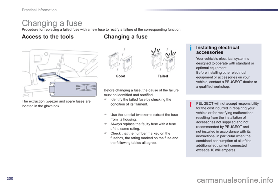
The extraction tweezer and spare
fuses are
located in the glove box.
Access to the tools
Before changing a fuse, the cause of the failure
must be identified and rectified. F Identify the failed fuse by checking thecondition of its filament.
Changing a fuse
Good Failed
F
Use the special tweezer to extract the fuse from its housing.F
Always replace the faulty fuse with a fuse of the same rating.F
Check that the number marked on thefusebox, the rating marked on the fuse and
the following tables all agree.
PEUGEOT will not accept responsibilityfor the cost incurred in repairing your vehicle or for rectifying malfunctions resulting from the installation of accessories not supplied and not
recommended by PEUGEOT andnot installed in accordance with its instructions, in par ticular when thecombined consumption of all of the additional equipment connectedexceeds 10 milliamperes.
Installing electricalaccessories
Your vehicle's electrical system isdesigned to operate with standard or optional equipment.
Before installing other electrical equipment or accessories on your vehicle, contact a PEUGEOT dealer or a qualified workshop.
Page 203 of 340
8
201
Practical information
Access to the fuses
FOpen the glove box. FRemove the plastic cover.
Fuse N°
Rating (A)Functions
F6 A or B 15
Audio s
ystem.
F
83 Alarm.
F1
310 Front cigarette lighter.
F1410
Front 12 V socket.
F1
63 Rear courtesy lamp, rear map reading lamps.
F17
3 Front cour tesy lamp, cour tesy mirror.
F2
8 A or B15 Audio system.
F3
020 Rear wiper.
F32 10
Audio amplifier.
Page 204 of 340
202
Practical information
Dashboard fuses
The fusebox is placed in the lower dashboard (right-hand side).
Access to the fuses
FOpen the folding panel then apply pressure
to bypass the stops.
Fuse N°Rating (A)Functions
F
315 Driver's electric window panel, 12 V socket for rear seats.
F415
12 V socket in boot.
F5
30 One-touch rear window.
F
630 One-touch front window.
F1
120
Trailer unit.
F1220
Audio amplifier.
F1
520
Panoramic sunroof blind (SW).
F1
65
Driver's electric window switch panel.
Page 205 of 340
8
203
Practical information
Engine compartment
fuses
Fuse N°
Rating (A)Functions
F20 15
Front / rear screenwash pump.
F2
120 Headlamp wash pump.
F2215 Horn.
F2
315 Right-hand main beam headlamp.
F2
415 Left-hand main beam headlamp.
F27 5
Le
ft hand lamp mask.
F2
85 Right hand lamp mask. The fusebox is placed in the engine compartment near the battery.
Access to the fuses
F
Unclip the cover. F
Change the fuse (see corresponding paragraph).F
When you have finished, close the cover carefully to ensure correct sealing of thefusebox.
Page 206 of 340

204
Practical information
12 V battery
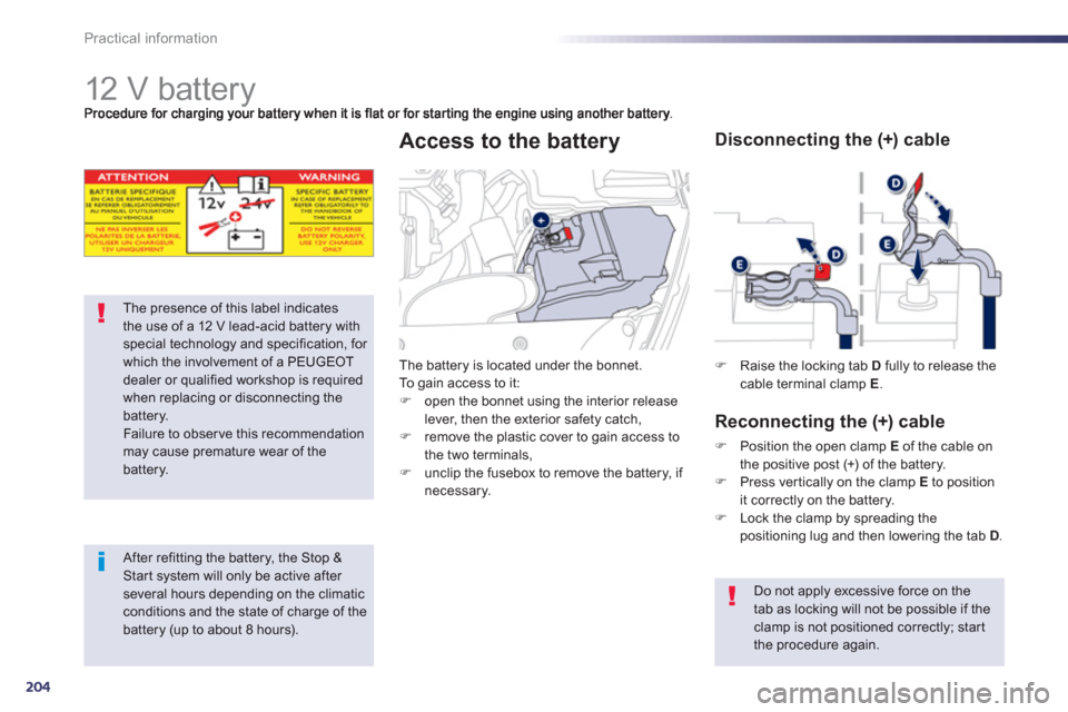
The presence of this label indicatesthe use of a 12 V lead-acid battery withspecial technology and specification, for which the involvement of a PEUGEOT dealer or qualified workshop is requiredwhen replacing or disconnecting thebattery.
Failure to observe this recommendation may cause premature wear of thebattery.
After refitting the battery, the Stop & Start system will only be active after several hours depending on the climaticconditions and the state of charge of the battery (up to about 8 hours).
The battery is located under the bonnet.
To gain access to it:
F
open the bonnet using the interior releaselever, then the exterior safety catch, F
remove the plastic cover to gain access to
the two terminals,F unclip the fusebox to remove the battery, if necessary.
Access to the battery
F
Raise the locking tab Dfully to release the cable terminal clamp E.
Disconnecting the (+) cable
Reconnectin
g the (+) cable
F
Position the open clamp Eof the cable on
the positive post (+) of the battery.
F Press ver tically on the clamp E
to position
it correctly on the battery. F Lock the clamp by spreading the positioning lug and then lowering the tab D.
Do not apply excessive force on the
tab as locking will not be possible if the clamp is not positioned correctly; star tthe procedure again.
Page 221 of 340
9
219
Checks
The various caps and covers allow access for checking the levels of the various fluids and for
replacing cer tain components.
Petrol engines
1.
Power steering reservoir.2.Screenwash and headlamp wash reservoir.3.Coolant reservoir.4.
Brake fluid reservoir.
5. Battery / Fuses.
6.Fusebox.
7. Air filter.8.Engine oil dipstick.9.
Engine oil filler cap.
1.6 litre 16V VTi 120 hp
1.6 litre 16V THP 155 hp
Page 222 of 340
220
Checks
checking the levels of the various fluids, for replacing cer tain components and for primingthe fuel system.
*
Accordin
g to engine.
Diesel engines
1.
Power steering reservoir.2.
Screenwash and headlamp wash reservoir.3.
Coolant reservoir. 4.
Brake fluid reservoir.5.
Battery / Fuses.
6.Fusebox.
7. Air filter.8.Engine oil dipstick. 9.
Engine oil filler cap.10.Priming pump * . 11.
Bleed screw *
. 1.6 litre HDi 110 hp
2.0 litre HDi 140 hp