2013 PEUGEOT 3008 parking brake
[x] Cancel search: parking brakePage 163 of 352
161
D
R
STOP & START
The Stop & Start system puts the engine
temporarily into standby - STOP mode -
during stops in the traffi c (red lights, traf-
fi c jams, or other...). The engine restarts
automatically - START mode - as soon as
you want to move off. The restart takes
place instantly, quickly and silently.
Perfect for urban use, the Stop & Start
system reduces fuel consumption and
exhaust emissions as well as the noise
level when stationary.
Operation
Going into engine STOP mode
The "ECO"
warning lamp comes
on in the instrument panel and
the engine goes into standby:
- with the electronic gearbox sys-
tem
, at speeds below 4 mph (6 km/h),
press the brake pedal or put the gear
lever in position N
.
If your vehicle is fi tted with the system,
a time counter calculates the sum of the
periods in STOP mode during a journey.
It rests itself to zero every time the igni-
tion is switched on with the key.
For your comfort, during park-
ing maoeuvres, STOP mode is
not available for a few seconds
after coming out of reverse gear.
STOP mode does not affect the func-
tionality of the vehicle, such as for
example, braking, power steering...
Never refuel with the engine in
STOP mode; you must switch
off the ignition with the key.
Special cases: STOP mode not
available
STOP mode is not invoked when:
- the driver's door is open,
- the driver's seat belt is not fastened,
- the vehicle has not exceeded 6 mph
(10 km/h) since the last engine start
using the key,
- the electric parking brake is applied
or being applied,
- the engine is needed to maintain a
comfortable temperature in the pas-
senger compartment,
- demisting is active,
- some special conditions (battery
charge, engine temperature, brak-
ing assistance, ambient tempera-
ture...) where the engine is needed
to assure control of a system.
In this case, the "ECO"
warning
lamp fl ashes for a few seconds
then goes off.
This operation is perfectly normal.
Page 164 of 352
162
D
R
I
Going into engine START mode
The "ECO"
warning lamp goes
off and the engine starts with the
electronic gearbox
system
:
- gear lever in position A
or M
, release
the brake pedal,
- or gear lever in position N
and the
brake pedal released, move the
gear lever to position A
or M
,
- or engage reverse gear.
In this case the "ECO"
warning
lamp fl ashes for a few seconds,
then goes off.
Special cases: START invoked
automatically
START mode is invoked automatically
when:
- the driver's door is open,
- the driver's seat belt is not fas-
tened,
- the speed of the vehicle exceeds
7 mph (11 km/h) with the electronic
gearbox system,
- the electric parking brake is being
applied,
- some special conditions (battery
charge, engine temperature, brak-
ing assistance, ambient tempera-
ture...) where the engine is needed
for control of a system.
This operation is perfectly normal.
Deactivation
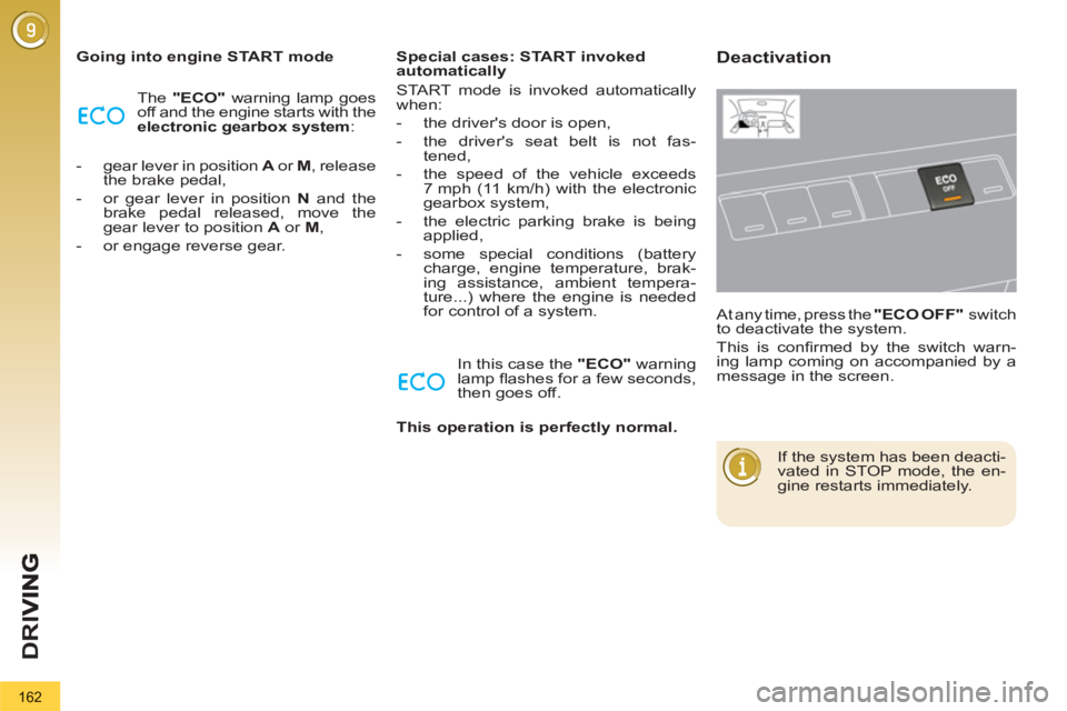
At any time, press the "ECO OFF"
switch
to deactivate the system.
This is confi rmed by the switch warn-
ing lamp coming on accompanied by a
message in the screen.
If the system has been deacti-
vated in STOP mode, the en-
gine restarts immediately.
Page 176 of 352
174
CHECKS
Brake disc wear
Brake pads
Brake wear depends on the
style of driving, particularly in
the case of vehicles used in
town, over short distances. It
may be necessary to have the
condition of the brakes checked, even
between vehicle services.
Unless there is a leak in the circuit, a
drop in the brake fl uid level indicates
that the brake pads are worn.
For information on checking
brake disc wear, contact a
PEUGEOT dealer or a quali-
fi ed workshop.
Manual gearbox
The gearbox does not re-
quire any maintenance (no oil
change).
Refer to the servicing booklet for
the details of the level checking
interval for this component.
6-speed electronic
gearbox
The gearbox does not re-
quire any maintenance (no oil
change).
Refer to the servicing booklet
for details of the checking in-
terval for this component.
Automatic gearbox
The gearbox does not re-
quire any maintenance (no oil
change).
Refer to the servicing booklet
for details of the level checking
interval for this component. This system does not require any
routine servicing. However, in
the event of a problem, have the
system checked by a PEUGEOT
dealer or a qualifi ed workshop.
Electric parking brake
For more information, refer to the "Electric
parking brake - Operating faults" section.
Only use products recommended by
PEUGEOT or products of equivalent
quality and specifi cation.
In order to optimise the operation of
units as important as the braking sys-
tem, PEUGEOT selects and offers very
specifi c products.
To avoid damaging the electrical units, the
use of a high pressure washer in the en-
gine compartment is strictly prohibited
.
Page 177 of 352
175
PRACTICAL INFORMATION
TEMPORARY PUNCTURE REPAIR KIT
The kit is stowed in the boot under the
fl oor. It is installed in the tool box, lo-
cated under the storage box.
Complete system consisting of a com-
pressor and a sealant cartridge which
permits temporary repair
of a tyre so
that you can drive to the nearest ga-
rage.
It is designed to repair most punctures
which could affect the tyre, located on
the tyre tread or shoulder.
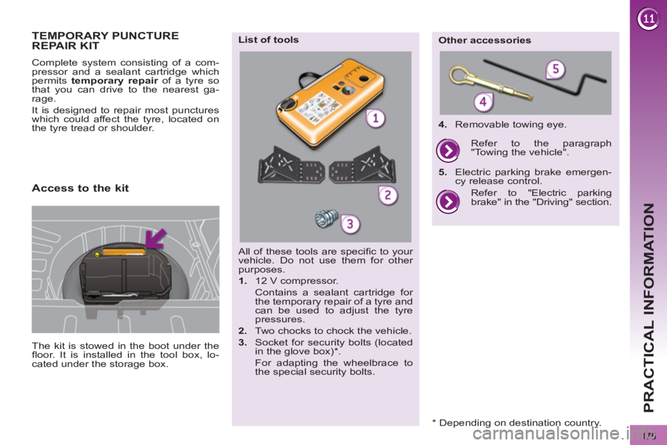
All of these tools are specifi c to your
vehicle. Do not use them for other
purposes.
1.
12 V compressor.
Contains a sealant cartridge for
the temporary repair of a tyre and
can be used to adjust the tyre
pressures.
2.
Two chocks to chock the vehicle.
3.
Socket for security bolts (located
in the glove box) * .
For adapting the wheelbrace to
the special security bolts.
List of tools
Other accessories
4.
Removable towing eye.
Refer to "Electric parking
brake" in the "Driving" section.
Refer to the paragraph
"Towing the vehicle".
5.
Electric parking brake emergen-
cy release control.
Access to the kit
* Depending on destination country.
Page 184 of 352
182
PRACTICAL INFORMATION
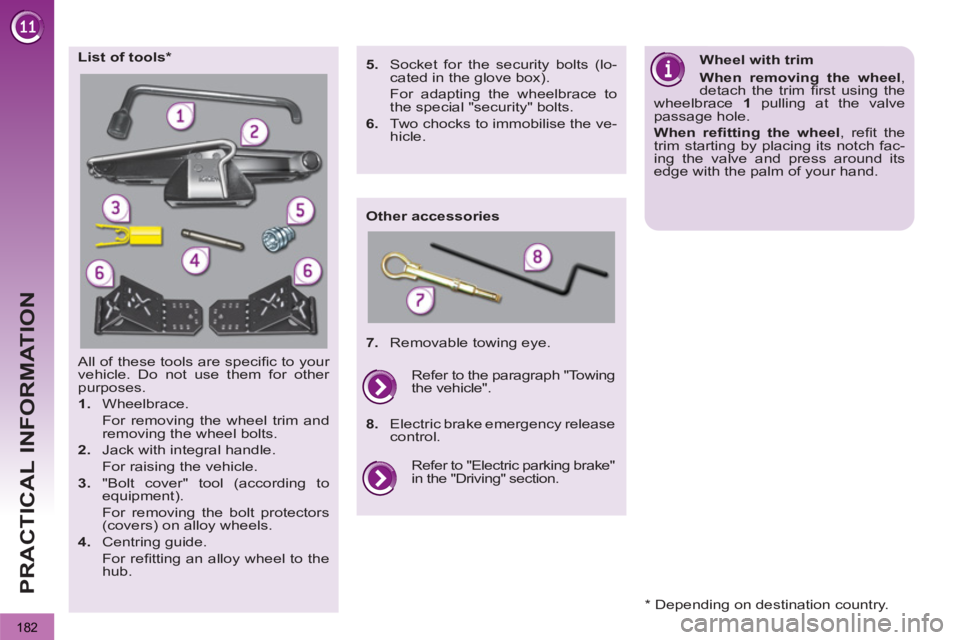
All of these tools are specifi c to your
vehicle. Do not use them for other
purposes.
1.
Wheelbrace.
For removing the wheel trim and
removing the wheel bolts.
2.
Jack with integral handle.
For raising the vehicle.
3.
"Bolt cover" tool (according to
equipment).
For removing the bolt protectors
(covers) on alloy wheels.
4.
Centring guide.
For refi tting an alloy wheel to the
hub.
List of tools *
Other accessories
Wheel with trim
When removing the wheel
,
detach the trim fi rst using the
wheelbrace 1
pulling at the valve
passage hole.
When refi tting the wheel
, refi t the
trim starting by placing its notch fac-
ing the valve and press around its
edge with the palm of your hand.
5.
Socket for the security bolts (lo-
cated in the glove box).
For adapting the wheelbrace to
the special "security" bolts.
6.
Two chocks to immobilise the ve-
hicle.
7.
Removable towing eye.
Refer to "Electric parking brake"
in the "Driving" section. Refer to the paragraph "Towing
the vehicle".
8.
Electric brake emergency release
control.
* Depending on destination country.
Page 186 of 352

184
PRACTICAL INFORMATION
Parking the vehicle
Immobilise the vehicle where
it does not block traffi c: the
ground must be level, stable and
non-slippery ground.
Apply the parking brake unless it
has been programmed to automatic
mode, switch off the ignition and en-
gage fi rst gear * to lock the wheels.
Check that the braking warning lamp
and the P
warning lamp on the park-
ing brake control come on.
If necessary, place a chock under the
wheel diagonally opposite the wheel
to be changed.
The occupants must get out of the ve-
hicle and wait where they are safe.
Never go underneath a vehicle raised
using a jack; use an axle stand.
Removing a wheel
List of operations
�)
Remove the bolt cover from each of
the bolts using the tool 3
(according
to equipment).
�)
Fit the security socket 5
on the
wheelbrace 1
to slacken the security
bolt (if your vehicle has them).
�)
Slacken the other bolts using the
wheelbrace 1
only.
�)
Place the jack 2
in contact with one
of the two front A
or rear B
locations
provided on the underbody, which-
ever is closest to the wheel to be
changed.
�)
Extend the jack 2
until its base plate
is in contact with the ground. Ensure
that the centreline of the jack base
plate is directly below the location A
or B
used.
�)
Raise the vehicle until there is suf-
fi cient space between the wheel and
the ground to admit the spare (not
punctured) wheel easily.
�)
Remove the bolts and store them in
a clean place.
�)
Remove the wheel.
*
position R
for the electronic gear
control gearbox; P
for the automatic
gearbox.
Page 199 of 352
197
PRACTICAL INFORMATION
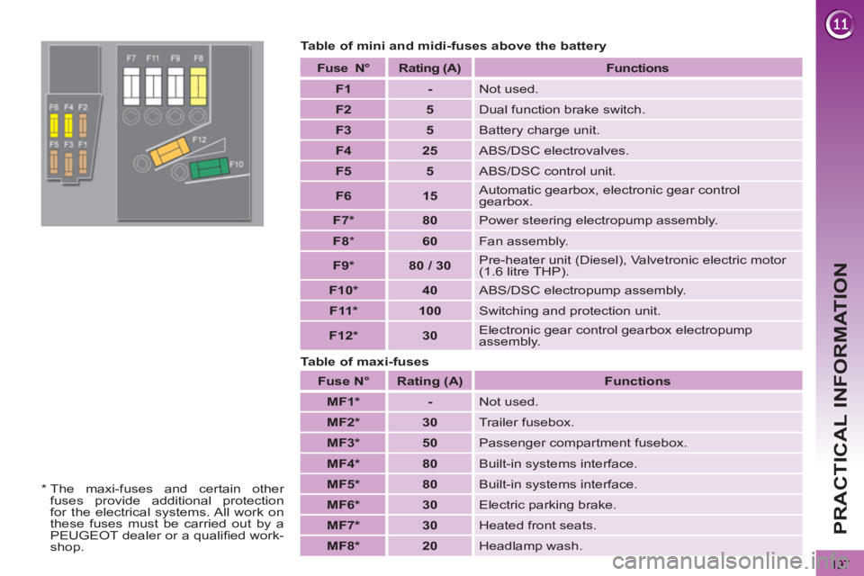
Table of mini and midi-fuses above the battery
Fuse
N°
Rating
(A)
Functions
F1
-
Not used.
F2
5
Dual function brake switch.
F3
5
Battery charge unit.
F4
25
ABS/DSC electrovalves.
F5
5
ABS/DSC control unit.
F6
15
Automatic gearbox, electronic gear control
gearbox.
F7 *
80
Power steering electropump assembly.
F8
*
60
Fan assembly.
F9 *
80 / 30
Pre-heater unit (Diesel), Valvetronic electric motor
(1.6 litre THP).
F10 *
40
ABS/DSC electropump assembly.
F11 *
100
Switching and protection unit.
F12 *
30
Electronic gear control gearbox electropump
assembly.
Fuse
N°
Rating
(A)
Functions
MF1 *
-
Not used.
MF2 *
30
Trailer fusebox.
MF3 *
50
Passenger compartment fusebox.
MF4 *
80
Built-in systems interface.
MF5 *
80
Built-in systems interface.
MF6 *
30
Electric parking brake.
MF7 *
30
Heated front seats.
MF8 *
20
Headlamp wash.
Table of maxi-fuses
*
The maxi-fuses and certain other
fuses provide additional protection
for the electrical systems. All work on
these fuses must be carried out by a
PEUGEOT dealer or a qualifi ed work-
shop.
Page 205 of 352
203
PRACTICAL INFORMATION
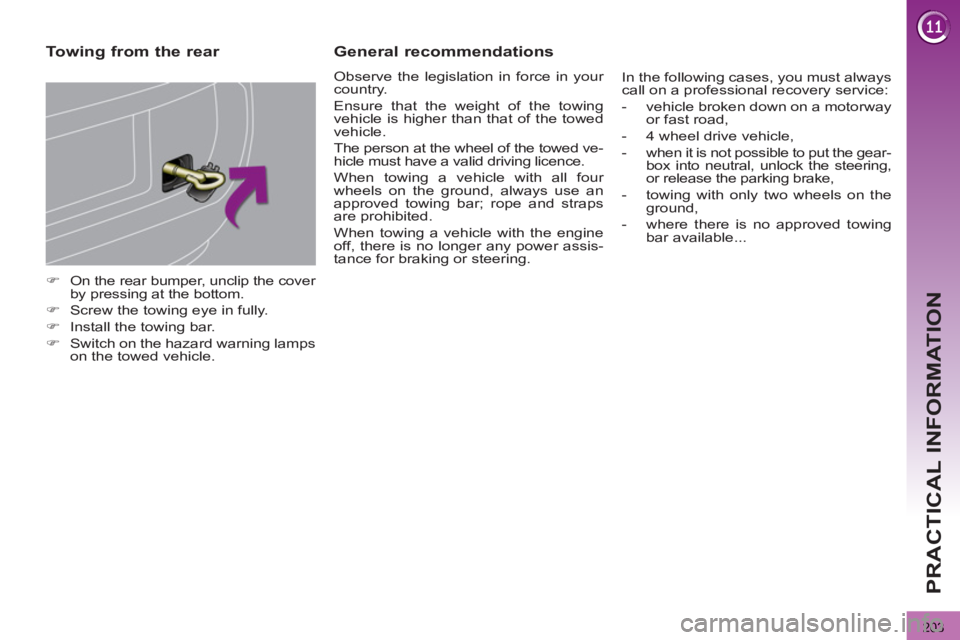
�)
On the rear bumper, unclip the cover
by pressing at the bottom.
�)
Screw the towing eye in fully.
�)
Install the towing bar.
�)
Switch on the hazard warning lamps
on the towed vehicle.
Towing from the rear
General recommendations
Observe the legislation in force in your
country.
Ensure that the weight of the towing
vehicle is higher than that of the towed
vehicle.
The person at the wheel of the towed ve-
hicle must have a valid driving licence.
When towing a vehicle with all four
wheels on the ground, always use an
approved towing bar; rope and straps
are prohibited.
When towing a vehicle with the engine
off, there is no longer any power assis-
tance for braking or steering. In the following cases, you must always
call on a professional recovery service:
- vehicle broken down on a motorway
or fast road,
- 4 wheel drive vehicle,
- when it is not possible to put the gear-
box into neutral, unlock the steering,
or release the parking brake,
- towing with only two wheels on the
ground,
- where there is no approved towing
bar available...