Page 339 of 394
Removing the headlight bulb
1. Open the hood.
2. Disconnect the negative (-) battery cable.
3. Disconnect the electrical connector from therear end of the bulb. 4. Turn the bulb retaining ring counterclock-
wise until it is free from the headlight reflec-
tor and then remove it
�A.
5. Carefully remove the headlight bulb. Do not shake or rotate the bulb when removing it
�B.
Replacing the headlight bulb
1. Insert the bulb.
DO NOT TOUCH THE BULB WITH BARE
HANDS.
2. Install and tighten the bulb retainer. ●Be sure the lip of the bulb socket con-
tacts the headlight body.
3. Push the electrical connector into the bulb plastic base until it snaps and stops.
4. Connect the negative (-) battery cable.
5. Close the hood.
WDI0294
8-30Maintenance and do-it-yourself
Page 340 of 394
EXTERIOR AND INTERIOR LIGHTS
ItemWattage (W)Bulb No.*1
Headlight 65/559007 (HB5)
Turn signal light/Parking light 28/83457AK
Side marker 3.8194
Off road lights*
260 9005LL (HB3)
Rear combination light Turn signal 273156
Stop/Tail 27/83157KX RD
Back-up 18921
License plate light 5168
Fog light (if so equipped)*
255 H11
Interior light 8AL48
Map lights 8AL48
Cargo light 8AL48
High-mounted stop light*
2— LED
*1Always check with the Parts Department at a NISSAN dealer for the latest parts information.
*2The bulb is not serviceable in-vehicle. See a NISSAN dealer for assistance.
Maintenance and do-it-yourself8-31
Page 341 of 394
1. Map light
2. Off road light (if so equipped)
3. Interior light
4. Fog light (if so equipped)
5. Headlight assembly
6. Cargo light
7. High-mounted stoplight
8. Rear combination light
9. License plate light
Replacement procedures
All other lights are either type A, B, C or D. When
replacing a bulb, first remove the lens and/or
cover.
WDI0671
WDI0295
8-32Maintenance and do-it-yourself
Page 342 of 394
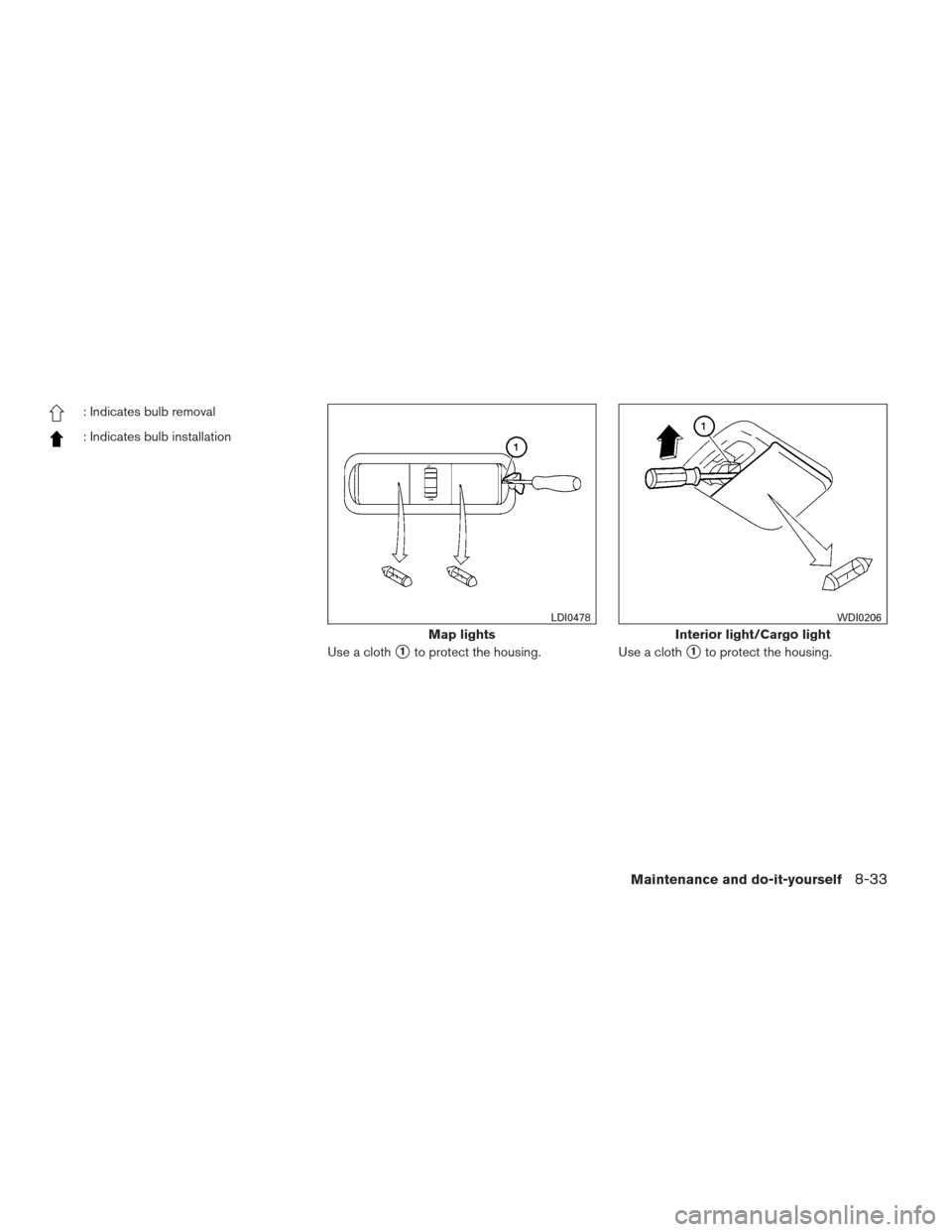
: Indicates bulb removal
: Indicates bulb installationUse a cloth
�1to protect the housing.Use a cloth�1to protect the housing.
Map lights
LDI0478
Interior light/Cargo light
WDI0206
Maintenance and do-it-yourself8-33
Page 343 of 394

This vehicle is equipped with the Tire
Press")
If you have a flat tire, see “Flat tire” in the
“In case of emergency” section of this
manual.
TIRE PRESSURE
Tire Pressure Monitoring System
(TPMS)
This vehicle is equipped with the Tire
Pressure Monitoring System (TPMS) . It
monitors tire pressure of all tires except
the spare. When the low tire pressure
warning light is lit and the CHECK TIRE
PRES (pressure) warning message is dis-
played in the odometer, one or more of
your tires is significantly under-inflated.
The TPMS will activate only when the
vehicle is driven at speeds above 16 MPH
(25 km/h). Also, this system may not de-
tect a sudden drop in tire pressure (for
example a flat tire while driving) .
For more details, refer to “Low tire pres-
sure warning light” in the “Instruments and
controls” section, “Tire Pressure Monitor-
ing System (TPMS)” in the “Starting and
driving” section, and “Flat tire” in the “In
case of emergency” section.
Tire inflation pressure
Check the tire pressures (including the
spare) often and always prior to long dis-
tance trips. The recommended tire pres-
sure specifications are shown on the
F.M.V.S.S./C.M.V.S.S. certification label
or the Tire and Loading Information label
under the “Cold Tire Pressure” heading.
The Tire and Loading Information label is
affixed to the driver side center pillar. Tire
pressures should be checked regularly
because:● Most tires naturally lose air over time.
● Tires can lose air suddenly when
driven over potholes or other objects
or if the vehicle strikes a curb while
parking.
The tire pressures should be checked
when the tires are cold. The tires are
considered COLD after the vehicle has
been parked for 3 or more hours, or driven
less than 1 mile (1.6 km) at moderate
speeds.
Rear combination light
LDI0448
WHEELS AND TIRES
8-34Maintenance and do-it-yourself
Page 344 of 394

Incorrect tire pressure, including un-
der inflation, may adversely affect
tire life and vehicle handling.
WARNING
● Improperly inflated tires can fail
suddenly and cause an accident.
● The Gross Vehicle Weight Rating
(GVWR) is located on the
F.M.V.S.S./C.M.V.S.S. certifica-
tion label. The vehicle weight ca-
pacity is indicated on the Tire and
Loading Information label. Do
not load your vehicle beyond this
capacity. Overloading your ve-
hicle may result in reduced tire
life, unsafe operating conditions
due to premature tire failure, or
unfavorable handling character-
istics and could also lead to a
serious accident. Loading be-
yond the specified capacity may
also result in failure of other ve-
hicle components. ●
Before taking a long trip, or
whenever you heavily load your
vehicle, use a tire pressure gauge
to ensure that the tire pressures
are at the specified level.
● For additional information re-
garding tires, refer to “Important
Tire Safety Information” (US) or
“Tire Safety Information”
(Canada) in the Warranty Infor-
mation Booklet.
Maintenance and do-it-yourself8-35
Page 345 of 394
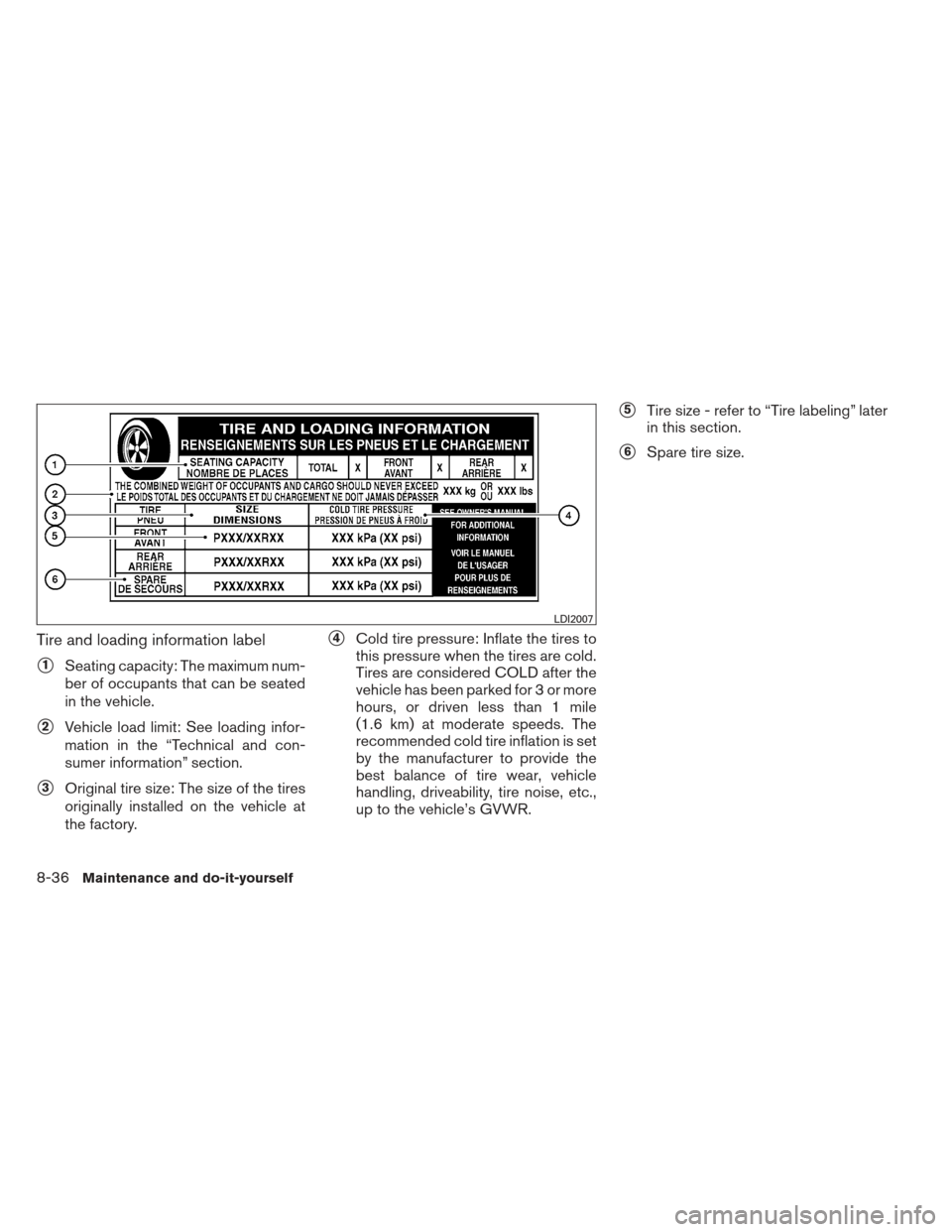
Tire and loading information label
�1Seating capacity: The maximum num-
ber of occupants that can be seated
in the vehicle.
�2Vehicle load limit: See loading infor-
mation in the “Technical and con-
sumer information” section.
�3Original tire size: The size of the tires
originally installed on the vehicle at
the factory.
�4Cold tire pressure: Inflate the tires to
this pressure when the tires are cold.
Tires are considered COLD after the
vehicle has been parked for 3 or more
hours, or driven less than 1 mile
(1.6 km) at moderate speeds. The
recommended cold tire inflation is set
by the manufacturer to provide the
best balance of tire wear, vehicle
handling, driveability, tire noise, etc.,
up to the vehicle’s GVWR.
�5Tire size - refer to “Tire labeling” later
in this section.
�6Spare tire size.
LDI2007
8-36Maintenance and do-it-yourself
Page 346 of 394

Checking tire pressure
1. Remove the valve stem cap from thetire.
2. Press the pressure gauge squarely onto the valve stem. Do not press too
hard or force the valve stem side-
ways, or air will escape. If the hissing
sound of air escaping from the tire is
heard while checking the pressure,
reposition the gauge to eliminate this
leakage. 3. Remove the gauge.
4. Read the tire pressure on the gauge
stem and compare to the specifica-
tion shown on the Tire and Loading
Information label.
5. Add air to the tire as needed. If too much air is added, press the core of
the valve stem briefly with the tip of
the gauge stem to release pressure.
Recheck the pressure and add or
release air as needed.
6. Install the valve stem cap.
7. Check the pressure of all other tires, including the spare.
4WD model
Size Cold Tire Infla-
tion Pressure
Front Original Tire:
P265/65R17
P265/70R16
P265/75R16 240 kPa, 35 PSI
4WD model
Rear Original Tire:
P265/65R17
P265/70R16
P265/75R16 240 kPa, 35 PSI
Spare Tire:
P265/65R17
P265/70R16
P265/75R16 240 kPa, 35 PSI
2WD model
Size Cold Tire Infla-
tion Pressure
Front Original Tire:
P265/70R16 250 kPa, 36 PSI
Rear Original Tire:
P265/70R16 250 kPa, 36 PSI
Spare Tire:
P265/70R16 250 kPa, 36 PSI
LDI0393
Maintenance and do-it-yourself8-37
 battery cable.
3. Disconnect the electrical connector from therear end of the bulb. 4. Turn the bulb retaining ring counter")
Bulb No.*1
Headlight 65/559007 (HB5)
Turn signal light/Parking light 28/83457AK
Side marker 3.8194
Off road lights*
260 9005LL (HB3)
Rear combination light")

3. Interior light
4. Fog light (if so equipped)
5. Headlight assembly
6. Cargo light
7. High-mounted stoplight
8. Rear combination light
9. License plat")