Page 7 of 44
1-1.2 Interior Component Location
Interior
components referenced in this manual are as follows: Charging indicator lights
Power switch
Hood r
elease Selector lever
READY indicator (green)
Charge connector
lock switch
AAYIA0044GB7
Page 14 of 44
4. Apply foot brake and press the ignition switch to turn the system ON. Confirm READY
indicator in instrument cluster turns ON.
5. Check Li-ion battery available charge gauge: a. If remaining energy (1) shows higher than half full (7 of 12 gauge lines lit up) , continue to next step.
b. If remaining energy (2) shows lower than half full (6 of 12 gauge lines lit up) , discharging is not needed.
6. Turn ON electric devices such as headlamps, cabin heater (set to the highest temperature and maximum fan speed; do not use AUTO A/C setting) , navigation system and rear window defogger
to discharge the Li-ion battery. Allow approximately 30 minutes for each line on the available
charge gauge to drop. Discharge is complete when the available charge gauge drops to lower
than half full (6 of 12 gauge lines lit up) .
7. Press the power switch to turn the system OFF. LOCK Acc
(OFF) ON AAYIA0036GB
0
1 POWER
Brake
P A 120miles
0.0miles MPH
PM
F miles 1 2
AAYIA0148ZZ
14
Page 17 of 44
3-3.1 Removing the Charge Connector
NO
TE:
Use the illustration to identify the type of charge connector and follow the appropriate
procedure.
1.Quick Charge Connector (If So Equipped)
NOTE:
The quick charger must be OFF to release the charge connector lock.
Release the quick connector lock and pull to remove. Refer to the quick charger label or
instructions.
2. Trickle and Normal Charge Connectors
a. Press the charge connector release button on the charge connector and pull to remove.
NOTE:
If the charge connector cannot be removed, the electric lock is engaged. Follow
the next steps to disengage.
b. To disengage the electric charge connector lock, place the charge connector lock switch in the
UNLOCK mode (center level position) . Trickle and Normal Charge Connector
T
ypical Quick Charge Connector
AAYIA0047GB
LOCKAUTO AAYIA0152ZZ
17
Page 18 of 44
c. The charge connector can be unlocked by
pushing the charge connector unlock button on
the Nissan Intelligent Key® for more than 1
second. The charge connector will temporarily
unlock for 30 seconds.
d. Press the charge connector release button and pull the charge connector to remove it.
3. If the Trickle or Normal Charge Connector Cannot Unlock
a. Place power switch in OFF position.
b. Open the hood.
c. Using the jack rod from the tool set located in the cargo area (or suitable tool) , insert into the screw
located through the access hole near the front
of the hood lock.
d. Rotate screw clockwise to release the charge connector lock.
e. Press the charge connector release button and pull the charge connector to remove it. HOLD
NISSAN
AAYIA0153ZZ
AAYIA0091ZZ
AAYIA0145ZZ
AAYIA0154ZZ
18
Page 19 of 44

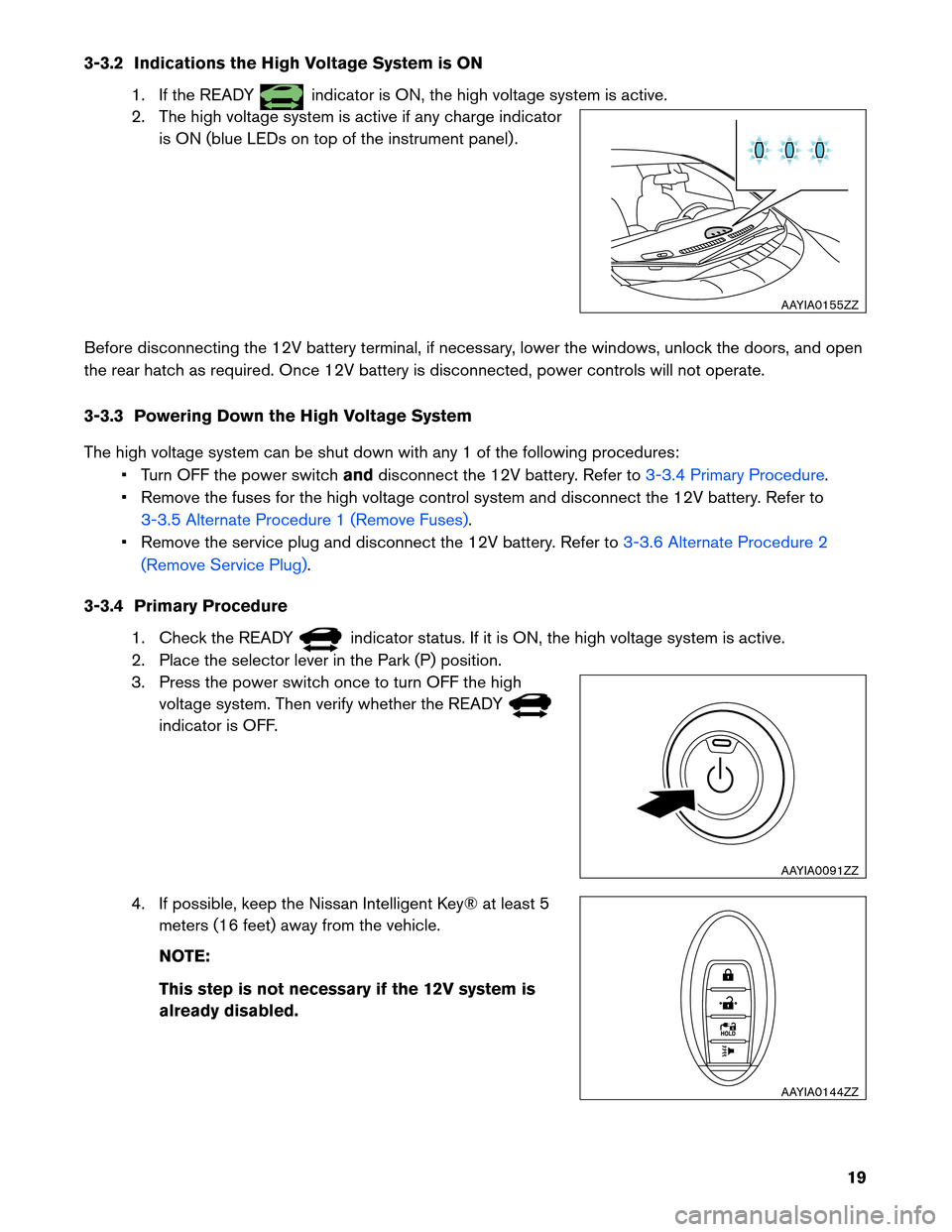
3-3.2 Indications the High Voltage System is ON
1. If the READY indicator is ON, the high voltage system is active.
2.
The high voltage system is active if any charge indicator
is ON (blue LEDs on top of the instrument panel) .
Before disconnecting the 12V battery terminal, if necessary, lower the windows, unlock the doors, and open
the rear hatch as required. Once 12V battery is disconnected, power controls will not operate.
3-3.3 Powering Down the High Voltage System
The high voltage system can be shut down with any 1 of the following procedures: • Turn OFF the power switch anddisconnect the 12V battery. Refer to
3-3.4 Primary Procedure.
•
Remove the fuses for the high voltage control system and disconnect the 12V battery. Refer to
3-3.5 Alternate Procedure 1 (Remove Fuses).
•
Remove the service plug and disconnect the 12V battery. Refer to 3-3.6 Alternate Procedure 2
(Remove
Service Plug) .
3-3.4
Primary Procedure
1. Check the READY indicator status. If it is ON, the high voltage system is active.
2.
Place the selector lever in the Park (P) position.
3. Press the power switch once to turn OFF the high voltage system. Then verify whether the READY indicator is OFF.
4.
If possible, keep the Nissan Intelligent Key® at least 5
meters (16 feet) away from the vehicle.
NOTE:
This step is not necessary if the 12V system is
already disabled. AAYIA0155ZZ
AAYIA0091ZZ
HOLD
AAYIA0144ZZ
19
Page 24 of 44
3. Remove the service plug using the following steps: (1) pull up and release the green lever, (2)
press the locking tab to release and rotate fully upward, (3) pull the service plug completely out of
its socket.
4. Wait at least ten (10) minutes for complete discharge of the high voltage capacitor after
the service plug has been removed.
5. Open the hood.
6. Disconnect the negative (-) 12V battery cable (1) . Insulate the negative (-) battery cable terminal with
insulated tape.
NOTE: : Arrow in illustration depicts vehicle front
direction. 1
2
3
Pull up Rotate
Push to
release Pull up
and
remove
AAYIA0048GB AAYIA0145ZZ
1
AAYIA0149ZZ
24
Page 40 of 44
4. Disconnect the cabin heater harness connector (A) from
the Li-ion battery. Touching high voltage components without wearing
appropriate
Personal Protective Equipment (PPE) will
cause electrocution.
a. Use the following instructions to disconnect thecabin heater harness connector. To prevent electrocution, cover battery side of high
voltage
connector with insulated tape (A) . : Insulated tape
5.
Disconnect the Li-ion battery vehicle communications
connector (A) while turning it counterclockwise. Touching high voltage components without wearing
appropriate
Personal Protective Equipment (PPE) will
cause electrocution.
A
AAYIA0171ZZ 1
3 4
2
Pull back lock tab
Press release and
pull connector
Disconnect connector
AAYIA0050GB AAYIA0172ZZ
A
AAYIA0167ZZ
40