2013 NISSAN GT-R power steering
[x] Cancel search: power steeringPage 17 of 346
GTR-10GT-R Overview
.Drive with the suspension setup switch in
the COMF mode to allow more suspension
stroke.
600 to 1,200 miles (1,000 to 2,000 km):
. Drive with the engine speed kept relatively
high with the shift lever in the
&Mposition.
Shifting is recommended between 1st and
4th gears.
. Avoid unnecessary quick steering and
abrupt braking.
. Drive with the suspension setup switch in
the COMF mode to allow more suspension
stroke.
Even though the mileage reaches over 1,200
miles (2,000 km) , the clutch may take longer to
properly engage if the vehicle is mainly driven in
town at a low speed. NISSAN recommends
breaking in the clutch at a GT-R certified
NISSAN dealer.
WHEEL ALIGNMENT
Do not adjust the wheel alignment until the
mileage reaches 1,000 miles (1,600 km). Until
then, the suspension may not engage enough
and the height may be higher.
However, make sure to adjust the alignment
after 1,000 miles (1,600 km) .
The wheel alignment can be adjusted by a GT-R certified NISSAN dealer in accordance with
specifications for city driving to high perfor-
mance driving.
The tires on the GT-R may have different wear
rates and wear patterns in comparison to
conventional passenger vehicles. Contact a
GT-R certified NISSAN dealer to confirm that
the alignment is within specifications.
VEHICLE DYNAMIC CONTROL (VDC)
OFF MODE
Always make sure the VDC is ON before driving
the vehicle by checking that the VDC OFF
indicator lights on the meter and the VDC set-up
switch are not illuminated. The GT-R is a high
performance vehicle and the VDC must be on/
activated to provide proper powertrain operation
and intended drivability.
WARNING
.
The VDC OFF mode should ONLY be
used briefly to help free the vehicle
if stuck in snow or mud by tempora-
rily stopping operation of the VDC
to maintain wheel torque.
. Driving the GT-R with the VDC off
may lead to handling issues related
to steering maneuvers, acceleration,
or deceleration. Moreover, driving
with the VDC off can result in an
inoperative vehicle by causing ser-
ious damage to the powertrain,
including damage to the Transaxle
Assembly including Transfer, Clutch,
Gears, Transaxle case and all of its
components and other drivetrain
PRECAUTIONS BEFORE DRIVING
Page 22 of 346
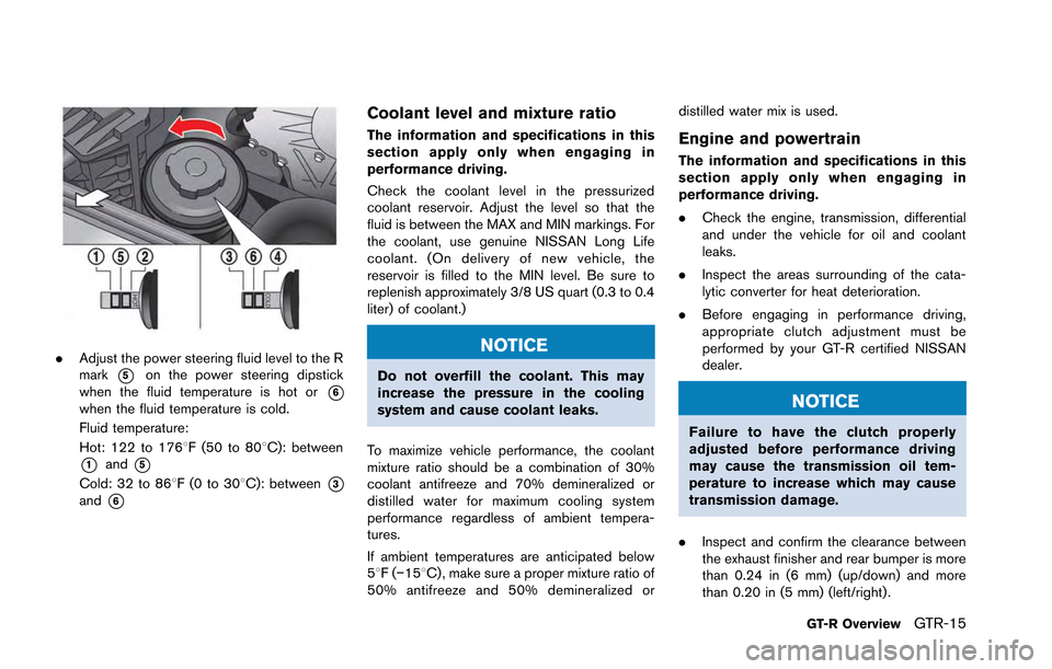
.Adjust the power steering fluid level to the R
mark
*5on the power steering dipstick
when the fluid temperature is hot or
*6when the fluid temperature is cold.
Fluid temperature:
Hot: 122 to 1768F (50 to 808C): between
*1and*5
Cold: 32 to 868F(0to30 8C): between*3and*6
Coolant level and mixture ratio
The information and specifications in this
section apply only when engaging in
performance driving.
Check the coolant level in the pressurized
coolant reservoir. Adjust the level so that the
fluid is between the MAX and MIN markings. For
the coolant, use genuine NISSAN Long Life
coolant. (On delivery of new vehicle, the
reservoir is filled to the MIN level. Be sure to
replenish approximately 3/8 US quart (0.3 to 0.4
liter) of coolant.)
NOTICE
Do not overfill the coolant. This may
increase the pressure in the cooling
system and cause coolant leaks.
To maximize vehicle performance, the coolant
mixture ratio should be a combination of 30%
coolant antifreeze and 70% demineralized or
distilled water for maximum cooling system
performance regardless of ambient tempera-
tures.
If ambient temperatures are anticipated below
58F( −158C) , make sure a proper mixture ratio of
50% antifreeze and 50% demineralized or distilled water mix is used.
Engine and powertrain
The information and specifications in this
section apply only when engaging in
performance driving.
.
Check the engine, transmission, differential
and under the vehicle for oil and coolant
leaks.
. Inspect the areas surrounding of the cata-
lytic converter for heat deterioration.
. Before engaging in performance driving,
appropriate clutch adjustment must be
performed by your GT-R certified NISSAN
dealer.
NOTICE
Failure to have the clutch properly
adjusted before performance driving
may cause the transmission oil tem-
perature to increase which may cause
transmission damage.
. Inspect and confirm the clearance between
the exhaust finisher and rear bumper is more
than 0.24 in (6 mm) (up/down) and more
than 0.20 in (5 mm) (left/right) .
GT-R OverviewGTR-15
Page 30 of 346
Suspension and wheel alignment
.Check the steering and suspension system
and other links for loose and/or damaged
parts.
. Measure and adjust the wheel alignment.
Contact a GT-R certified NISSAN dealer to
adjust the wheel alignment to the recom-
mended setting for normal driving.
Wheels and tires
.Check tire wear and cracking.
. Inspect the tire side wall for damage.
. Check the tire pressure and adjust the
pressure as necessary when the tires are
cold. (
“Wheels and tires” page GTR-
16) If you do not drive under the conditions
listed in this section, see (
“Wheels and
tires” page 8-31)
. Check that the wheel nuts are not stripped.
Check if there is no deformation on the
contact surface of the wheel nuts.
. Make sure the wheel nuts are tight.
(
“Wheels and tires” page 8-31)
. Make sure the drive shaft nuts are tight.
. Check wheel hub run out and that the wheel
rotates smoothly without any friction. Check
these with the tires removed whenever an inspection is performed with the vehicle
jacked up.
. Make sure the tire has not slipped on the
wheel causing the assembly to be out of
balance. The reference marks on the tire and
wheel should be aligned. If the reference
marks are not aligned, the tire has slipped on
the wheel. Have the wheels/tires reba-
lanced. Make sure the old reference marks
are erased and new reference marks are
applied to the wheel and tire. When instal-
ling new tires on the wheels, make sure new
reference marks are applied to the wheels
and tires. (
“Wheels and tires” page
GTR-16)
. Make sure that the TPMS sensor installation
nuts and the sensor valve are tight and there
is no nitrogen leak.
Brakes
.Check for the heat deterioration of the
brakes and parts around the brakes.
. Check the condition of the brake pads and
disc rotors and replace them as necessary.
Engine and powertrain
.Check the engine, transmission, differential
and under the vehicle for oil and coolant leaks.
. Inspect the area surrounding the catalytic
converter for heat deterioration.
. Inspect and confirm the clearance between
the exhaust finisher and rear bumper is more
than 0.24 in (6 mm) (up/down) and more
than 0.20 in (5 mm) (left/right) .
. The clutch clearance and shift fork position
may need to be adjusted.
. Inspect the dust boot of the drive shaft
universal joint for cracks or damage.
. Check that there is no abnormal noise,
vibrations or warning lights illuminated when
making tight turns at slow speed (for tight
corner braking phenomenon) .
GT-R OverviewGTR-23
Page 47 of 346
0-10Illustrated table of contents
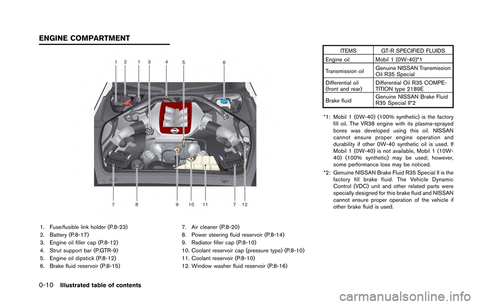
1. Fuse/fusible link holder (P.8-23)
2. Battery (P.8-17)
3. Engine oil filler cap (P.8-12)
4. Strut support bar (P.GTR-9)
5. Engine oil dipstick (P.8-12)
6. Brake fluid reservoir (P.8-15)7. Air cleaner (P.8-20)
8. Power steering fluid reservoir (P.8-14)
9. Radiator filler cap (P.8-10)
10. Coolant reservoir cap (pressure type) (P.8-10)
11. Coolant reservoir (P.8-10)
12. Window washer fluid reservoir (P.8-16) ITEMS GT-R SPECIFIED FLUIDS
Engine oil Mobil 1 (0W-40)*1
Transmission oil Genuine NISSAN Transmission
Oil R35 Special
Differential oil
(front and rear) Differential Oil R35 COMPE-
TITION type 2189E
Brake fluid Genuine NISSAN Brake Fluid
R35 Special II*2
*1: Mobil 1 (0W-40) (100% synthetic) is the factory fill oil. The VR38 engine with its plasma-sprayed
bores was developed using this oil. NISSAN
cannot ensure proper engine operation and
durability if other 0W-40 synthetic oil is used. If
Mobil 1 (0W-40) is not available, Mobil 1 (10W-
40) (100% synthetic) may be used; however,
some performance loss may be noticed.
*2: Genuine NISSAN Brake Fluid R35 Special II is the factory fill brake fluid. The Vehicle Dynamic
Control (VDC) unit and other related parts were
specially designed for this brake fluid and NISSAN
cannot ensure proper operation of the vehicle if
other brake fluid is used.
ENGINE COMPARTMENT
Page 97 of 346
Cruise control system warning .................................... 2-39
Low fuel warning ............................................................. 2-39
Door/trunk open warning .............................................. 2-40
Low washer fluid warning ............................................. 2-40
No key warning ................................................................ 2-40
Operation displays ................................................................ 2-41 Engine start operation indicator .................................. 2-41
Shift “P” warning ............................................................. 2-42
“PUSH” warning .............................................................. 2-42
Steering lock release malfunction indicator ............. 2-42
Intelligent Key insertion indicator ................................ 2-43
Intelligent Key removal indicator .................................. 2-43
Intelligent Key battery discharge indicator ................ 2-43
Security systems ................................................................... 2-44
Vehicle security system ................................................. 2-44
NISSAN Vehicle Immobilizer System ......................... 2-45
Windshield wiper and washer switch .............................. 2-46 Using the wipers ............................................................. 2-47
Using the washer ............................................................ 2-48
Rear window defroster switch ........................................... 2-48
Headlight and turn signal switch ...................................... 2-49
Xenon headlights ............................................................. 2-49
Headlight switch .............................................................. 2-49
Hazard warning flasher switch .......................................... 2-52
Horn ........................................................................\
.................. 2-53 Heated seats (if so equipped) .......................................... 2-53
Turning on the heaters ................................................. 2-53
Turning off the heaters ................................................. 2-53
Power outlets ........................................................................\
2-54
Storage ........................................................................\
........... 2-55 Cup holders .................................................................... 2-55
Sunglasses holder ........................................................ 2-56
Door pocket .................................................................... 2-57
Glove box ........................................................................\
2-57Console box ................................................................... 2-58
Coat hooks ..................................................................... 2-58
Windows ........................................................................\
........ 2-59 Power windows ............................................................. 2-59
Interior lights ........................................................................\
.. 2-61
Map lights ....................................................................... 2-61
Interior light control switch ......................................... 2-62
Vanity mirror lights ................................................................ 2-63
HomeLink
®Universal Transceiver .................................... 2-63
Programming HomeLink®............................................ 2-64
Programming HomeLink®for
Canadian customers .................................................... 2-65
Operating the HomeLink
®universal transceiver ... 2-65
Programming trouble-diagnosis ................................ 2-65
Clearing the programmed information ..................... 2-66
Reprogramming a single HomeLink
®button ......... 2-66
If your vehicle is stolen ................................................ 2-66
Page 162 of 346
3 Pre-driving checks and adjustments
Keys ........................................................................\
..................... 3-2Intelligent Key ...................................................................... 3-2
Doors ........................................................................\
................... 3-4
Locking with inside lock knob ........................................ 3-5
Locking with power door lock switch ........................... 3-5
Automatic door lock system ............................................ 3-5
Locking with mechanical key ........................................... 3-6
Opening the doors ............................................................ 3-7
Intelligent Key system ............................................................. 3-8 Intelligent Key functions .................................................... 3-9
Remote keyless entry functions ................................... 3-12
Setting hazard indicator and horn mode .................. 3-13
Warning signals ............................................................... 3-16
Troubleshooting guide ................................................... 3-17
Hood ........................................................................\
................. 3-18 Opening the hood ........................................................... 3-18
Closing the hood ............................................................. 3-19 Trunk ........................................................................\
................ 3-20
Trunk open request switch ......................................... 3-20
Trunk lid release switch ............................................... 3-20
Trunk release power cancel switch .......................... 3-21Opening and closing the trunk .................................. 3-21
Emergency trunk lid release ....................................... 3-22
Fuel-filler door ....................................................................... 3-23 Opening the fuel filler door ........................................ 3-24
Closing the fuel-filler door .......................................... 3-25
Steering wheel ...................................................................... 3-26
Tilt/telescopic steering column .................................. 3-26
Sun visors ........................................................................\
....... 3-27
Mirrors ........................................................................\
............. 3-27
Inside mirror .................................................................... 3-27
Outside mirrors .............................................................. 3-28
Vanity mirror .................................................................... 3-29
Page 194 of 346
5 Starting and driving
Precautions when starting and driving ............................... 5-3Exhaust gas (carbon monoxide) ..................................... 5-3Three-way catalyst ............................................................. 5-3
Tire Pressure Monitoring System (TPMS) ................... 5-4
Avoiding collision and rollover ........................................ 5-7
Off-road recovery ............................................................... 5-7
Rapid air pressure loss ..................................................... 5-8
Drinking alcohol/drugs and driving ................................ 5-8All-Wheel Drive (AWD) driving safety precautions .... 5-9
Push-button ignition switch ................................................... 5-9
Operating range for engine start ................................ 5-10
Ignition switch operation ............................................... 5-10
Ignition switch positions ................................................ 5-10
Emergency engine shut off ........................................... 5-11
Intelligent Key battery discharge ................................. 5-11
Before starting the engine .................................................. 5-13
Starting the engine ............................................................... 5-13
Driving the vehicle ................................................................ 5-15 Dual clutch transmission ............................................... 5-15
Driving tips ........................................................................\
5-21
VDC, transmission and suspension setup switches .... 5-24 How to switch the modes ............................................ 5-25
Features of each mode .................................................. 5-27 Turbocharger system ........................................................... 5-31
R mode start function ......................................................... 5-32
How to use R mode start function ........................... 5-33
Parking brake ........................................................................\
. 5-33
Cruise control ........................................................................\
5-34 Precautions on cruise control .................................... 5-35
Steering-wheel-mounted controls ............................ 5-35
Indicators and display .................................................. 5-36
Cruise control operations ........................................... 5-36
Hill Start Assist ..................................................................... 5-38
Break-in schedule ................................................................ 5-39 Wheel alignment ........................................................... 5-39
Increasing fuel economy ..................................................... 5-40
All-Wheel Drive (AWD) ...................................................... 5-41 AWD warning light ....................................................... 5-41
Tight corner braking phenomenon ........................... 5-42
Tires ........................................................................\
.......... 5-43AWD system characteristics ...................................... 5-43
Limited Slip Differential (LSD) .......................................... 5-44
Parking/parking on hills ....................................................... 5-45
Power steering ...................................................................... 5-46
Brake system ........................................................................\
. 5-47 Braking precautions ..................................................... 5-47
Parking brake break-in ................................................. 5-47
Page 204 of 346
NOTE:
.If the steering lock release malfunction
indicator appears on the vehicle infor-
mation display when the ignition
switch is pressed, press the ignition
switch again while gently turning the
steering wheel left and right.
(
“Steering lock release malfunc-
tion indicator” page 2-42)
. If the shift
&Pwarning appears on the
vehicle information display when the
ignition switch is pushed, the shift lever
is in any position except the
&Pposi-
tion. Move the shift lever to the&Pposition. (“Shift “P” warning”
page 2-42)
. If the Intelligent Key battery discharge
indicator appears on the vehicle infor-
mation display, the Intelligent Key
battery is discharged and the ignition
switch will not operate. Insert the
Intelligent Key into the key port to
operate the ignition switch.
(
“Intelligent Key battery discharge
indicator” page 2-43)
. When all of the following conditions
are met for 60 minutes, the battery
saver system will cut off the power
supply to prevent battery discharge. —
The ignition switch is in the ACC
position, and
— All doors are closed, and
— The shift lever is in the
&Pposition.
. Do not leave the vehicle with the
ignition switch in the ACC or ON
position when the engine is not run-
ning for an extended period of time.
This can discharge the battery.
EMERGENCY ENGINE SHUT OFF
To shut off the engine in an emergency situation
while driving, perform the following procedure:
.Rapidly push the push-button ignition switch
3 consecutive times in less than 1.5
seconds, or
. Push and hold the push button ignition
switch for more than 2 seconds.
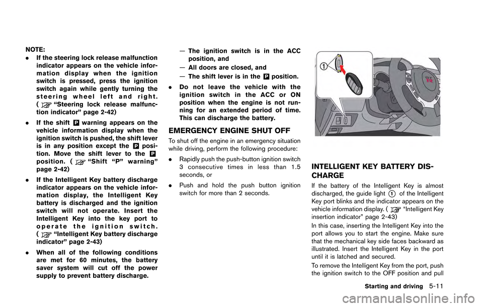
INTELLIGENT KEY BATTERY DIS-
CHARGE
If the battery of the Intelligent Key is almost
discharged, the guide light
*1of the Intelligent
Key port blinks and the indicator appears on the
vehicle information display. (
“Intelligent Key
insertion indicator” page 2-43)
In this case, inserting the Intelligent Key into the
port allows you to start the engine. Make sure
that the mechanical key side faces backward as
illustrated. Insert the Intelligent Key in the port
until it is latched and secured.
To remove the Intelligent Key from the port, push
the ignition switch to the OFF position and pull
Starting and driving5-11