Page 43 of 346
0-6Illustrated table of contents
1. Coat hooks (P.2-58)
2. Inside lock knob (P.3-5)
3. Interior light control switch (P.2-61)
4. Map lights (P.2-61)
5. Sun visors (P.3-27)
6. Sunglasses holder (P.2-56)7. Inside rearview mirror (P.2-63, P.3-27)
8. Center console box (P.2-58)
— USB memory operation*
—iPod
®player operation*
9. Cup holders (P.2-55)
10. Power window switches (P.2-59) 11. Window lock button (P.2-60)
12. Power door lock switch (P.3-5)
*: Refer to the separate Multi Function Display
Owner’s Manual.
PASSENGER COMPARTMENT
Page 44 of 346
1. Headlight and turn signal switch (P.2-49)
2. Paddle shifters (P.5-15)
3. Steering-wheel-mounted controls (left side)*
4. Meters and gauges (P.2-5)
5. Steering-wheel-mounted controls (right side)— MRK (Mark) switch*
— Cruise control (P.5-34) 6. Windshield wiper and washer switch (P.2-46)
7. VDC, transmission and suspension set up
switches (P.5-24)
8. Trunk lid release switch (P.3-20)
9. Hood release handle (P.3-18)
10. Intelligent Key port (P.5-11) 11. Horn (P.2-53)
12. Tilting/telescopic steering wheel lever (P.3-26)
13. Push-button ignition switch (P.5-9)
14. Parking brake (P.5-33, P.5-45)
15. Shift lever (P.5-15)
*: Refer to the separate Multi Function Display
Owner’s Manual.
Illustrated table of contents0-7
COCKPIT
Page 51 of 346

1-2Safety — Seats, seat belts and supplemental restraint system
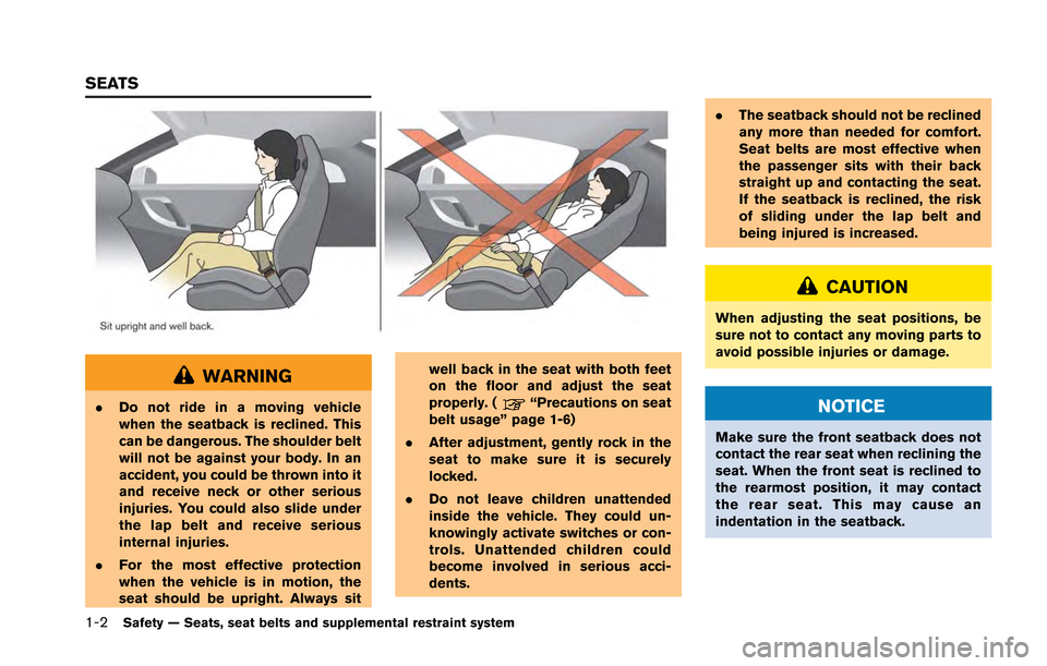
WARNING
.Do not ride in a moving vehicle
when the seatback is reclined. This
can be dangerous. The shoulder belt
will not be against your body. In an
accident, you could be thrown into it
and receive neck or other serious
injuries. You could also slide under
the lap belt and receive serious
internal injuries.
. For the most effective protection
when the vehicle is in motion, the
seat should be upright. Always sit well back in the seat with both feet
on the floor and adjust the seat
properly. (“Precautions on seat
belt usage” page 1-6)
. After adjustment, gently rock in the
seat to make sure it is securely
locked.
. Do not leave children unattended
inside the vehicle. They could un-
knowingly activate switches or con-
trols. Unattended children could
become involved in serious acci-
dents. .
The seatback should not be reclined
any more than needed for comfort.
Seat belts are most effective when
the passenger sits with their back
straight up and contacting the seat.
If the seatback is reclined, the risk
of sliding under the lap belt and
being injured is increased.
CAUTION
When adjusting the seat positions, be
sure not to contact any moving parts to
avoid possible injuries or damage.
NOTICE
Make sure the front seatback does not
contact the rear seat when reclining the
seat. When the front seat is reclined to
the rearmost position, it may contact
the rear seat. This may cause an
indentation in the seatback.
SEATS
Page 98 of 346
1. Headlight and turn signal switch (P.2-49)
2. Paddle shifters (P.5-15)
3. Steering-wheel-mounted controls (left side)*
4. Meters and gauges (P.2-5)
5. Steering-wheel-mounted controls (right side)— MRK (Mark) switch*
— Cruise control (P.5-34) 6. Windshield wiper and washer switch (P.2-46)
7. VDC, transmission and suspension set up
switches (P.5-24)
8. Trunk lid release switch (P.3-20)
9. Hood release handle (P.3-18)
10. Intelligent Key port (P.5-11) 11. Horn (P.2-53)
12. Tilting/telescopic steering wheel lever (P.3-26)
13. Push-button ignition switch (P.5-9)
14. Parking brake (P.5-33, P.5-45)
15. Shift lever (P.5-15)
*: Refer to the separate Multi Function Display
Owner’s Manual.
Instruments and controls2-3
COCKPIT
Page 106 of 346

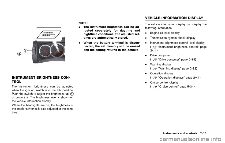
INSTRUMENT BRIGHTNESS CON-
TROL
The instrument brightness can be adjusted
when the ignition switch is in the ON position.
Push the switch to adjust the brightness up
*1or down*2. The brightness level is shown on
the vehicle information display.
When the headlights are on, the brightness of
the interior switches is also adjusted at the same
time. NOTE:
.
The instrument brightness can be ad-
justed separately for daytime and
nighttime conditions. The adjusted set-
tings are automatically stored.
. When the battery terminal is discon-
nected, the set memory will be erased
and the setting returns to the default.
The vehicle information display can display the
following information.
.Engine oil level display
. Transmission system check display
. Instrument brightness control level display
(
“Instrument brightness control” page
2-11)
. Drive computer
(
“Drive computer” page 2-14)
. Warning display
(
“Warning display” page 2-32)
. Operation display
(
“Operation displays” page 2-41)
. Cruise control display
(
“Cruise control” page 5-34)
Instruments and controls2-11
VEHICLE INFORMATION DISPLAY
Page 126 of 346

and then blinks for 10 seconds when the engine
is not running, it indicates that the vehicle is not
ready for an emission control system inspection/
maintenance test. (
“Readiness for Inspec-
tion/Maintenance (I/M) test (US only)” page 9-
20)
Operation:
The malfunction indicator light will come on in
one of two ways:
. Malfunction indicator light on steady — An
emission control system malfunction has
been detected. Check the fuel-filler cap. If
the fuel-filler cap is loose or missing, tighten
or install the cap and continue to drive the
vehicle. The
light should turn off after a
few driving trips. If thelight does not
turn off after a few driving trips, have the
vehicle inspected by a GT-R certified
NISSAN dealer. You do not need to have
your vehicle towed to the dealer.
. Malfunction indicator light blinking — An
engine misfire has been detected which may
damage the emission control system.
To reduce or avoid emission control system
damage:
a. Do not drive at speeds above 45 MPH
(72 km/h). b. Avoid hard acceleration or deceleration.
c. Avoid steep uphill grades.
d. If possible, reduce the amount of cargo
being hauled or towed.
The malfunction indicator light may stop
blinking and remain on.
Have the vehicle inspected by a GT-R
certified NISSAN dealer. You do not need
to have your vehicle towed to the dealer.
NOTICE
Continued vehicle operation without
having the emission control system
checked and repaired as necessary
could lead to poor driveability, reduced
fuel economy, and possible damage to
the emission control system.
Turn signal/hazard indicator
lights
The light flashes when the turn signal switch
lever or hazard switch is turned on.
Vehicle Dynamic Control (VDC)
off indicator light
The light comes on when the Vehicle Dynamic
Control (VDC) set up switch is pushed to OFF for more than 1 second. (
“VDC, transmis-
sion and suspension setup switches” page 5-
24)
This indicates that the vehicle dynamic control
system and traction control system are not
operating. (
“Vehicle Dynamic Control
(VDC) system” page 5-49)
AUDIBLE REMINDERS
Key reminder chime
A chime will sound if the driver side door is
opened while the ignition switch is pushed to
the ACC position or pushed to the OFF or
LOCK position with the Intelligent Key left in the
Intelligent Key port. Make sure the ignition
switch is pushed to the OFF position, and take
the Intelligent Key with you when leaving the
vehicle.
Light reminder chime
A chime will sound when the driver side door is
opened with the light switch in theorposition and the ignition switch in the ACC, OFF
or LOCK position.
Turn the light switch off when you leave the
vehicle.
Instruments and controls2-31
Page 154 of 346
NOTICE
Do not place items that are more than 2
lb (1 kg) on the hook.
POWER WINDOWS
WARNING
.Make sure that all passengers have
their hands, etc. inside the vehicle
while it is in motion and before
closing the windows. Use the win-
dow lock switch to prevent unex-
pected use of the power windows.
. Do not leave children unattended
inside the vehicle. They could un-
knowingly activate switches or con-
trols and become trapped in the
window. Unattended children could
become involved in serious acci-
dents.
The power windows operate when the ignition
switch is in the ON position or for about 45
seconds after the ignition switch is pushed to
the LOCK position. If the driver’s or front
passenger’s door is opened during this period
of about 45 seconds, power to the windows is
canceled.
Driver’s side1. Window lock button
2. Driver’s window switch
3. Front passenger’s window switch
Instruments and controls2-59
WINDOWS
Page 155 of 346

2-60Instruments and controls
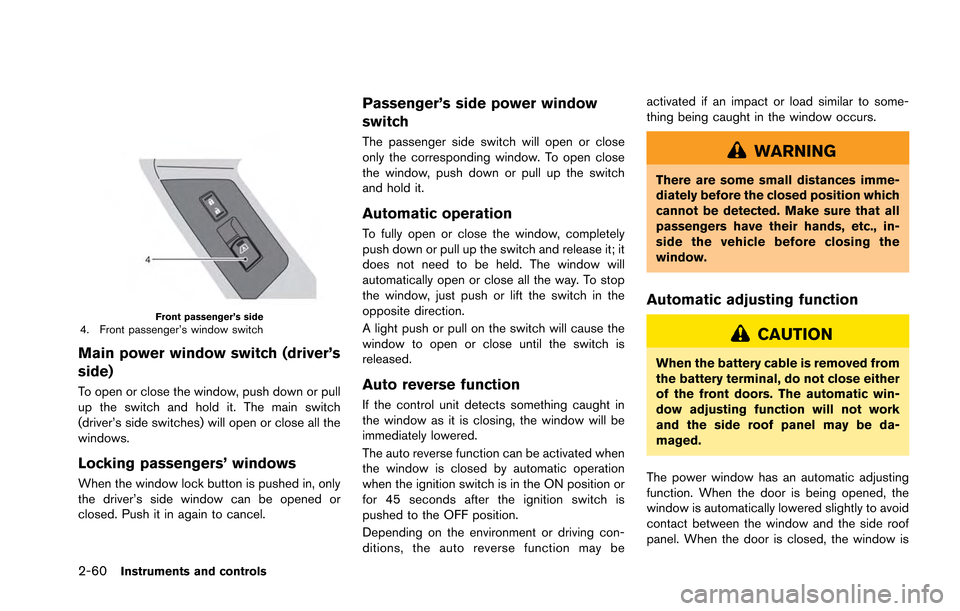
Front passenger’s side4. Front passenger’s window switch
Main power window switch (driver’s
side)
To open or close the window, push down or pull
up the switch and hold it. The main switch
(driver’s side switches) will open or close all the
windows.
Locking passengers’ windows
When the window lock button is pushed in, only
the driver’s side window can be opened or
closed. Push it in again to cancel.
Passenger’s side power window
switch
The passenger side switch will open or close
only the corresponding window. To open close
the window, push down or pull up the switch
and hold it.
Automatic operation
To fully open or close the window, completely
push down or pull up the switch and release it; it
does not need to be held. The window will
automatically open or close all the way. To stop
the window, just push or lift the switch in the
opposite direction.
A light push or pull on the switch will cause the
window to open or close until the switch is
released.
Auto reverse function
If the control unit detects something caught in
the window as it is closing, the window will be
immediately lowered.
The auto reverse function can be activated when
the window is closed by automatic operation
when the ignition switch is in the ON position or
for 45 seconds after the ignition switch is
pushed to the OFF position.
Depending on the environment or driving con-
ditions, the auto reverse function may beactivated if an impact or load similar to some-
thing being caught in the window occurs.
WARNING
There are some small distances imme-
diately before the closed position which
cannot be detected. Make sure that all
passengers have their hands, etc., in-
side the vehicle before closing the
window.
Automatic adjusting function
CAUTION
When the battery cable is removed from
the battery terminal, do not close either
of the front doors. The automatic win-
dow adjusting function will not work
and the side roof panel may be da-
maged.
The power window has an automatic adjusting
function. When the door is being opened, the
window is automatically lowered slightly to avoid
contact between the window and the side roof
panel. When the door is closed, the window is