2013 NISSAN GT-R parking brake
[x] Cancel search: parking brakePage 127 of 346
2-32Instruments and controls
Parking brake reminder chime
A chime will sound if the vehicle speed is above
4 MPH (7 km/h) with the parking brake applied.
Stop the vehicle and release the parking brake.
Reverse reminder chime (if so
equipped)
The chime will sound if the shift lever is in the&Rposition while the ignition switch is in the ON
position.
This is not a chime to remind people outside the
vehicle.
Be sure to move the shift lever out of the
&Rposition after driving in reverse.
Brake pad wear warning
The disc brake pads have audible wear warn-
ings. When a brake pad requires replacement, it
will make a high pitched scraping sound when
the vehicle is in motion. This scraping sound will
first occur only when the brake pedal is
depressed. After the wear of the brake pad is
increased, the sound will be heard all the time
even if the brake pedal is not depressed. Have
the brakes checked as soon as possible if the
warning sound is heard.
WARNING
When the warning light illuminates or
blinks and a warning is displayed,
promptly take the appropriate action.
Ignoring the warning may result inmalfunctions and accidents.
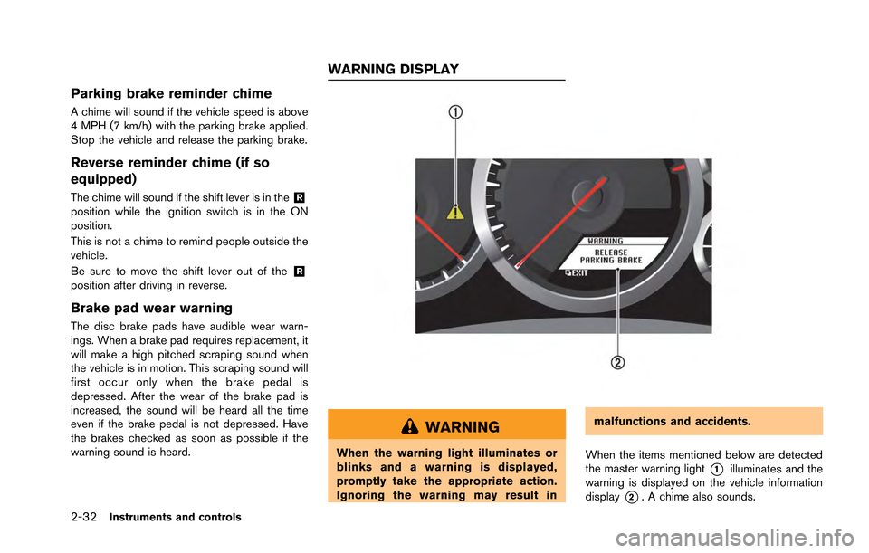
When the items mentioned below are detected
the master warning light
*1illuminates and the
warning is displayed on the vehicle information
display
*2. A chime also sounds.
WARNING DISPLAY
Page 130 of 346
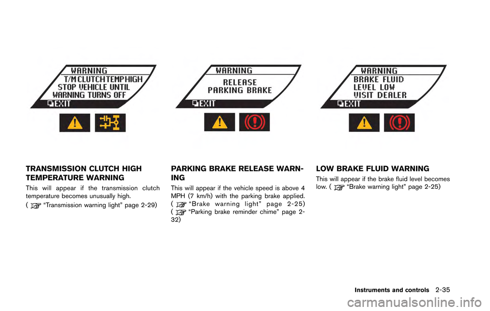
TRANSMISSION CLUTCH HIGH
TEMPERATURE WARNING
This will appear if the transmission clutch
temperature becomes unusually high.
(
“Transmission warning light” page 2-29)
PARKING BRAKE RELEASE WARN-
ING
This will appear if the vehicle speed is above 4
MPH (7 km/h) with the parking brake applied.
(
“Brake warning light” page 2-25)
(“Parking brake reminder chime” page 2-
32)
LOW BRAKE FLUID WARNING
This will appear if the brake fluid level becomes
low. (“Brake warning light” page 2-25)
Instruments and controls2-35
Page 146 of 346
CAUTION
Use low beams when there are cars
approaching from the opposite direc-
tion, during city driving and at similar
times.
Battery saver system
A chime will sound when the driver side door is
opened with the light switch in theorposition and the ignition switch in the ACC,
OFF or LOCK position. (“Light reminder
chime” page 2-31)
When the headlight switch is in the
orposition while the ignition switch is in the ON
position, the lights will automatically turn off 45
seconds after the ignition switch has been
pushed to the OFF position.
When the headlight switch remains in the
orposition after the lights automatically turn
off, the lights will turn on when the ignition
switch is pushed to the ON position.
NOTICE
. When you turn on the headlight
switch again after the lights auto-
matically turn off, the lights will not
turn off automatically. Be sure to
turn the light switch to the OFF
position when you leave the vehicle
for extended periods of time, other-
wise the battery will be discharged.
. Never leave the light switch on
when the engine is not running for
extended periods of time even if the
headlights turn off automatically.
Daytime running light system
The daytime running lights automatically illumi-
nate when the engine is started with the parking
brake released. The daytime running lights
operate with the headlight switch in the OFF
position. Turn the headlight switch to the
position for full illumination when driving at night.
If the parking brake is applied before the engine
is started, the daytime running lights do not
illuminate. The daytime running lights illuminate
once the parking brake is released. The daytime
running lights will remain on until the ignition
switch is pushed to the OFF position.
WARNING
When the daytime running light system
is active, tail lights on your vehicle are
not on. It is necessary at dusk to turn on
your headlights. Failure to do so could
cause an accident injuring yourself and
others.
Instruments and controls2-51
Page 194 of 346
5 Starting and driving
Precautions when starting and driving ............................... 5-3Exhaust gas (carbon monoxide) ..................................... 5-3Three-way catalyst ............................................................. 5-3
Tire Pressure Monitoring System (TPMS) ................... 5-4
Avoiding collision and rollover ........................................ 5-7
Off-road recovery ............................................................... 5-7
Rapid air pressure loss ..................................................... 5-8
Drinking alcohol/drugs and driving ................................ 5-8All-Wheel Drive (AWD) driving safety precautions .... 5-9
Push-button ignition switch ................................................... 5-9
Operating range for engine start ................................ 5-10
Ignition switch operation ............................................... 5-10
Ignition switch positions ................................................ 5-10
Emergency engine shut off ........................................... 5-11
Intelligent Key battery discharge ................................. 5-11
Before starting the engine .................................................. 5-13
Starting the engine ............................................................... 5-13
Driving the vehicle ................................................................ 5-15 Dual clutch transmission ............................................... 5-15
Driving tips ........................................................................\
5-21
VDC, transmission and suspension setup switches .... 5-24 How to switch the modes ............................................ 5-25
Features of each mode .................................................. 5-27 Turbocharger system ........................................................... 5-31
R mode start function ......................................................... 5-32
How to use R mode start function ........................... 5-33
Parking brake ........................................................................\
. 5-33
Cruise control ........................................................................\
5-34 Precautions on cruise control .................................... 5-35
Steering-wheel-mounted controls ............................ 5-35
Indicators and display .................................................. 5-36
Cruise control operations ........................................... 5-36
Hill Start Assist ..................................................................... 5-38
Break-in schedule ................................................................ 5-39 Wheel alignment ........................................................... 5-39
Increasing fuel economy ..................................................... 5-40
All-Wheel Drive (AWD) ...................................................... 5-41 AWD warning light ....................................................... 5-41
Tight corner braking phenomenon ........................... 5-42
Tires ........................................................................\
.......... 5-43AWD system characteristics ...................................... 5-43
Limited Slip Differential (LSD) .......................................... 5-44
Parking/parking on hills ....................................................... 5-45
Power steering ...................................................................... 5-46
Brake system ........................................................................\
. 5-47 Braking precautions ..................................................... 5-47
Parking brake break-in ................................................. 5-47
Page 203 of 346
5-10Starting and driving
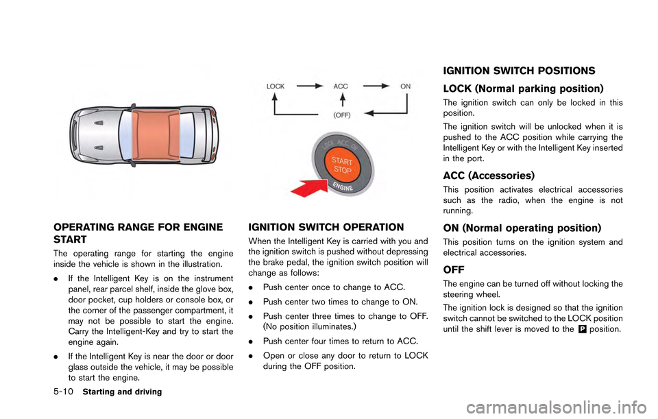
OPERATING RANGE FOR ENGINE
START
The operating range for starting the engine
inside the vehicle is shown in the illustration.
.If the Intelligent Key is on the instrument
panel, rear parcel shelf, inside the glove box,
door pocket, cup holders or console box, or
the corner of the passenger compartment, it
may not be possible to start the engine.
Carry the Intelligent-Key and try to start the
engine again.
. If the Intelligent Key is near the door or door
glass outside the vehicle, it may be possible
to start the engine.
IGNITION SWITCH OPERATION
When the Intelligent Key is carried with you and
the ignition switch is pushed without depressing
the brake pedal, the ignition switch position will
change as follows:
.Push center once to change to ACC.
. Push center two times to change to ON.
. Push center three times to change to OFF.
(No position illuminates.)
. Push center four times to return to ACC.
. Open or close any door to return to LOCK
during the OFF position.
IGNITION SWITCH POSITIONS
LOCK (Normal parking position)
The ignition switch can only be locked in this
position.
The ignition switch will be unlocked when it is
pushed to the ACC position while carrying the
Intelligent Key or with the Intelligent Key inserted
in the port.
ACC (Accessories)
This position activates electrical accessories
such as the radio, when the engine is not
running.
ON (Normal operating position)
This position turns on the ignition system and
electrical accessories.
OFF
The engine can be turned off without locking the
steering wheel.
The ignition lock is designed so that the ignition
switch cannot be switched to the LOCK position
until the shift lever is moved to the
&Pposition.
Page 206 of 346
.Make sure the area around the vehicle is
clear.
. Check fluid levels such as engine oil, cool-
ant, brake fluid and window washer fluid as
frequently as possible, or at least whenever
you refuel.
. Check that all windows and lights are clean.
. Visually inspect tires for their appearance
and condition. Also check tires for proper
inflation.
. Lock all doors.
. Position seat.
. Adjust inside and outside mirrors.
. Fasten seat belts and ask all passengers to
do likewise.
. Check the operation of warning lights when
the ignition switch is pushed to the ON
position. (
“Warning/indicator lights
and audible reminders” page 2-24)
NOTE:
. This vehicle includes spark plugs that
are designed for maximum perfor-
mance. If the start time becomes long-
er, the plugs may be fouled, making the
engine difficult to start. If this occurs,
start the engine using the procedure
described in this section.
. A click sound may be heard when the
brake pedal is depressed and released.
This is normal.
. A low rattling operating sound may
occur when the engine is started or
stopped. This is because of the trans-
mission gear design, light flywheel and
dry sump lubrication system used in
this transmission. This does not indi-
cate that there is a malfunction. This
sound is likely to occur in particular if
the engine is stopped when the tem-
perature of the transmission oil is high.
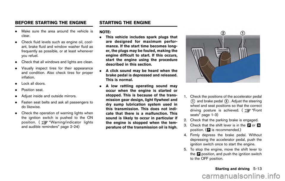
1. Check the positions of the accelerator pedal
*1and brake pedal*2. Adjust the steering
wheel and seat positions so that the correct
driving posture is achieved. (
“Front
seats” page 1-3)
2. Check that the parking brake is engaged.
3. Check that the shift lever is in the
&Por&Nposition. (&Pis recommended.)
4. Firmly depress the brake pedal. Without depressing the accelerator pedal, push the
ignition switch once to start the engine.
5. To stop the engine, move the shift lever to the
&Pposition, and push the ignition switch
to the OFF position.
Starting and driving5-13
BEFORE STARTING THE ENGINE STARTING THE ENGINE
Page 210 of 346
Shift lever operation
Push the button while depressing the
brake pedal.
Push the button.
Just move the shift lever.
Automatically returns.
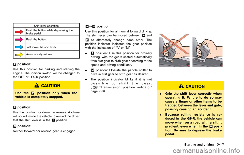
&Pposition:
Use this position for parking and starting the
engine. The ignition switch will be changed to
the OFF or LOCK position.
CAUTION
Use the&Pposition only when the
vehicle is completely stopped.
&Rposition:
Use this position for driving in reverse. A chime
will sound inside the vehicle to remind the driver
that the shift lever is in the
&Rposition.
&Nposition:
Neither forward nor reverse gear is engaged.
&A↔&Mposition:
Use this position for all normal forward driving.
The shift lever can be moved between
&Aand
&Mto alternately change each other. The
position indicator indicates the gear position
with the indication of “A” or “M”.
.
&Aposition: Use this position for ordinary
driving, with the gears shifted automatically
from first gear to sixth gear according to the
speed and driving conditions.
.
&Mposition: Operate the paddle shifter to
drive in first gear to sixth gear as desired.
. The position indicator blinks if it is not
possible to shift the gear.
(
“Transmission position indicator”
page 2-8)CAUTION
. Grip the shift lever correctly when
operating it. Failure to do so may
cause a finger or other items to be
trapped between the lever and gate,
possibly causing an accident.
. Because rolling resistance is re-
duced in the GT-R, the vehicle can
move when on a road with a slight
gradient, even when in the
&Nposi-
tion. Be sure to depress the brake
pedal.
Starting and driving5-17
Page 212 of 346
Shift lock release
If the battery charge is low or discharged, the
shift lever may not be moved from the&Pposition even with the brake pedal depressed
and the shift lever button pushed.
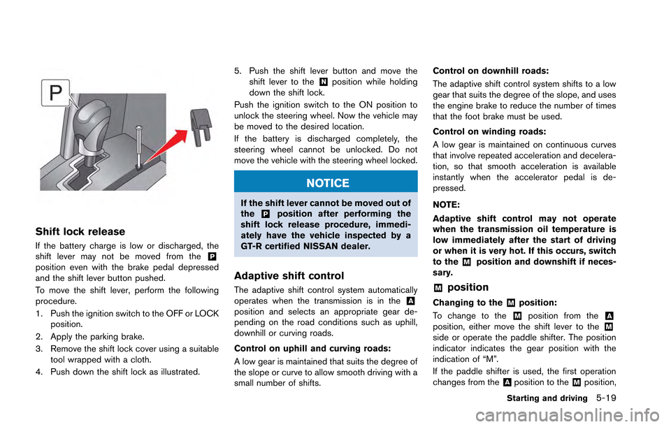
To move the shift lever, perform the following
procedure.
1. Push the ignition switch to the OFF or LOCKposition.
2. Apply the parking brake.
3. Remove the shift lock cover using a suitable tool wrapped with a cloth.
4. Push down the shift lock as illustrated. 5. Push the shift lever button and move the
shift lever to the
&Nposition while holding
down the shift lock.
Push the ignition switch to the ON position to
unlock the steering wheel. Now the vehicle may
be moved to the desired location.
If the battery is discharged completely, the
steering wheel cannot be unlocked. Do not
move the vehicle with the steering wheel locked.
NOTICE
If the shift lever cannot be moved out of
the&Pposition after performing the
shift lock release procedure, immedi-
ately have the vehicle inspected by a
GT-R certified NISSAN dealer.
Adaptive shift control
The adaptive shift control system automatically
operates when the transmission is in the&Aposition and selects an appropriate gear de-
pending on the road conditions such as uphill,
downhill or curving roads.
Control on uphill and curving roads:
A low gear is maintained that suits the degree of
the slope or curve to allow smooth driving with a
small number of shifts. Control on downhill roads:
The adaptive shift control system shifts to a low
gear that suits the degree of the slope, and uses
the engine brake to reduce the number of times
that the foot brake must be used.
Control on winding roads:
A low gear is maintained on continuous curves
that involve repeated acceleration and decelera-
tion, so that smooth acceleration is available
instantly when the accelerator pedal is de-
pressed.
NOTE:
Adaptive shift control may not operate
when the transmission oil temperature is
low immediately after the start of driving
or when it is very hot. If this occurs, switch
to the
&Mposition and downshift if neces-
sary.
&Mposition
Changing to the&Mposition:
To change to the
&Mposition from the&Aposition, either move the shift lever to the&Mside or operate the paddle shifter. The position
indicator indicates the gear position with the
indication of “M”.
If the paddle shifter is used, the first operation
changes from the
&Aposition to the&Mposition,
Starting and driving5-19