2013 NISSAN GT-R engine coolant
[x] Cancel search: engine coolantPage 46 of 346
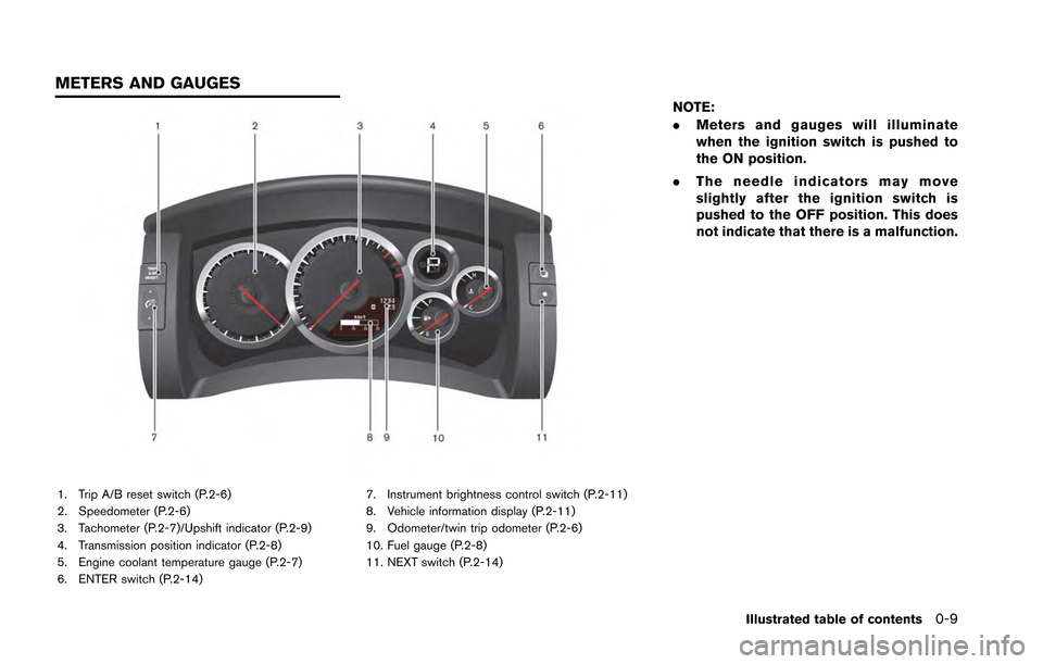
1. Trip A/B reset switch (P.2-6)
2. Speedometer (P.2-6)
3. Tachometer (P.2-7)/Upshift indicator (P.2-9)
4. Transmission position indicator (P.2-8)
5. Engine coolant temperature gauge (P.2-7)
6. ENTER switch (P.2-14)7. Instrument brightness control switch (P.2-11)
8. Vehicle information display (P.2-11)
9. Odometer/twin trip odometer (P.2-6)
10. Fuel gauge (P.2-8)
11. NEXT switch (P.2-14)
NOTE:
.
Meters and gauges will illuminate
when the ignition switch is pushed to
the ON position.
. The needle indicators may move
slightly after the ignition switch is
pushed to the OFF position. This does
not indicate that there is a malfunction.
Illustrated table of contents0-9
METERS AND GAUGES
Page 47 of 346
0-10Illustrated table of contents
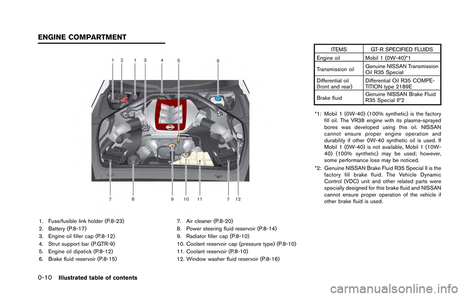
1. Fuse/fusible link holder (P.8-23)
2. Battery (P.8-17)
3. Engine oil filler cap (P.8-12)
4. Strut support bar (P.GTR-9)
5. Engine oil dipstick (P.8-12)
6. Brake fluid reservoir (P.8-15)7. Air cleaner (P.8-20)
8. Power steering fluid reservoir (P.8-14)
9. Radiator filler cap (P.8-10)
10. Coolant reservoir cap (pressure type) (P.8-10)
11. Coolant reservoir (P.8-10)
12. Window washer fluid reservoir (P.8-16) ITEMS GT-R SPECIFIED FLUIDS
Engine oil Mobil 1 (0W-40)*1
Transmission oil Genuine NISSAN Transmission
Oil R35 Special
Differential oil
(front and rear) Differential Oil R35 COMPE-
TITION type 2189E
Brake fluid Genuine NISSAN Brake Fluid
R35 Special II*2
*1: Mobil 1 (0W-40) (100% synthetic) is the factory fill oil. The VR38 engine with its plasma-sprayed
bores was developed using this oil. NISSAN
cannot ensure proper engine operation and
durability if other 0W-40 synthetic oil is used. If
Mobil 1 (0W-40) is not available, Mobil 1 (10W-
40) (100% synthetic) may be used; however,
some performance loss may be noticed.
*2: Genuine NISSAN Brake Fluid R35 Special II is the factory fill brake fluid. The Vehicle Dynamic
Control (VDC) unit and other related parts were
specially designed for this brake fluid and NISSAN
cannot ensure proper operation of the vehicle if
other brake fluid is used.
ENGINE COMPARTMENT
Page 96 of 346
2 Instruments and controls
Cockpit ........................................................................\
............... 2-3
Instrument panel ....................................................................... 2-4
Meters and gauges .................................................................. 2-5Speedometer ....................................................................... 2-6
Odometer/twin trip odometer ......................................... 2-6
Tachometer ........................................................................\
.. 2-7
Engine coolant temperature gauge ............................... 2-7
Fuel gauge ........................................................................\
... 2-8
Transmission position indicator ...................................... 2-8
Upshift indicator ................................................................. 2-9
Instrument brightness control ...................................... 2-11
Vehicle information display ................................................. 2-11 Engine oil level display ................................................... 2-12
Transmission system check display ............................ 2-13
Drive computer ...................................................................... 2-14 Current fuel consumption ............................................. 2-15
Vehicle speed ................................................................... 2-15
Cruise control ................................................................... 2-15
Average fuel consumption and speed ....................... 2-16
Elapsed time and trip odometer .................................. 2-16
Distance to empty ........................................................... 2-17
Outside air temperature ................................................ 2-17
Setting (drive computer) ............................................... 2-18
Warning (drive computer) ............................................. 2-23 Warning/indicator lights and audible reminders .......... 2-24
Checking bulbs ............................................................. 2-24
Warning lights ................................................................ 2-24
Indicator lights ............................................................... 2-61
Audible reminders ......................................................... 2-31
Warning display .................................................................... 2-32
Engine oil low pressure warning ............................... 2-33
Engine system warning ............................................... 2-33
Shift lever position warning ........................................ 2-34
Transmission system warning .................................... 2-34
Transmission oil high temperature warning ............ 2-34
Transmission clutch high temperature warning ..... 2-35Parking brake release warning .................................. 2-35
Low brake fluid warning .............................................. 2-35
Anti-lock Braking System (ABS) warning .............. 2-36
Vehicle Dynamic Control (VDC)
system warning .............................................................. 2-36
AWD clutch high temperature warning ................... 2-36
Front/rear tire size discrepancy warning ................. 2-37
AWD system warning .................................................. 2-37
Low tire pressure warning .......................................... 2-38
Run-flat tire warning ..................................................... 2-38Tire Pressure Monitoring System
(TPMS) warning ............................................................ 2-38
Page 100 of 346
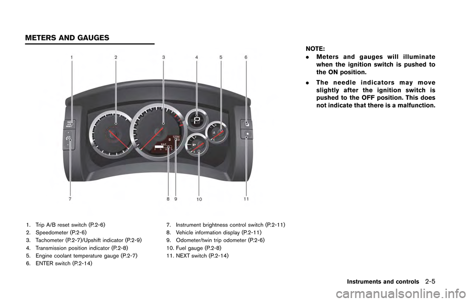
1. Trip A/B reset switch (P.2-6)
2. Speedometer (P.2-6)
3. Tachometer (P.2-7)/Upshift indicator (P.2-9)
4. Transmission position indicator (P.2-8)
5. Engine coolant temperature gauge (P.2-7)
6. ENTER switch (P.2-14)7. Instrument brightness control switch (P.2-11)
8. Vehicle information display (P.2-11)
9. Odometer/twin trip odometer (P.2-6)
10. Fuel gauge (P.2-8)
11. NEXT switch (P.2-14)
NOTE:
.
Meters and gauges will illuminate
when the ignition switch is pushed to
the ON position.
. The needle indicators may move
slightly after the ignition switch is
pushed to the OFF position. This does
not indicate that there is a malfunction.
Instruments and controls2-5
METERS AND GAUGES
Page 102 of 346
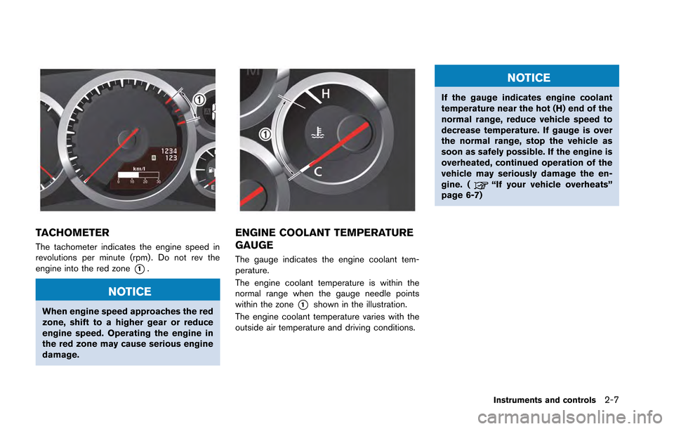
TACHOMETER
The tachometer indicates the engine speed in
revolutions per minute (rpm) . Do not rev the
engine into the red zone
*1.
NOTICE
When engine speed approaches the red
zone, shift to a higher gear or reduce
engine speed. Operating the engine in
the red zone may cause serious engine
damage.
ENGINE COOLANT TEMPERATURE
GAUGE
The gauge indicates the engine coolant tem-
perature.
The engine coolant temperature is within the
normal range when the gauge needle points
within the zone
*1shown in the illustration.
The engine coolant temperature varies with the
outside air temperature and driving conditions.
NOTICE
If the gauge indicates engine coolant
temperature near the hot (H) end of the
normal range, reduce vehicle speed to
decrease temperature. If gauge is over
the normal range, stop the vehicle as
soon as safely possible. If the engine is
overheated, continued operation of the
vehicle may seriously damage the en-
gine. (
“If your vehicle overheats”
page 6-7)
Instruments and controls2-7
Page 195 of 346
Brake assist ........................................................................\
.... 5-48Anti-lock Braking System (ABS) ................................ 5-48
Vehicle Dynamic Control (VDC) system ......................... 5-49
Cold weather driving ............................................................ 5-51
Freeing a frozen door lock ............................................ 5-51
Anti-freeze ........................................................................\
. 5-51 Battery ........................................................................\
...... 5-51
Draining of coolant water ............................................ 5-51
Tire equipment ............................................................... 5-52
Special winter equipment ........................................... 5-52
Driving on snow or ice ................................................ 5-52
Engine block heater (if so equipped) ...................... 5-53
Page 207 of 346
5-14Starting and driving
NOTE:
.If the engine is difficult to start, de-
press the accelerator pedal all the way
to the floor and hold it. Push the
ignition switch with the brake pedal
depressed to start cranking the engine.
After 5 or 6 seconds, stop cranking by
pushing the ignition switch to the OFF
position, and then release the accel-
erator pedal. Then perform steps 1 to 5
to start the engine. If the engine starts,
but fails to run, repeat this procedure.
. Starting and stopping the engine over a
short period of time may make the
vehicle more difficult to start. If this
occurs, wait for more than 3 minutes,
and then push the ignition switch again
to start the engine.
. To maintain high performance over a
long period of time, the engine speed is
limited to 5,000 rpm when the engine is
revved with the shift lever in the
&Nor
&Pposition, and to 4,000 rpm when the
engine oil or coolant temperature is
low or higher than normal.
. If the ignition switch is pushed before
the shift lever is moved to the
&Pposition, the ignition switch will not change to the OFF position. If this
occurs, the SHIFT
&Pwarning display
appears on the vehicle information
display. When stopping the engine, be
sure to move the shift lever to the
&Pposition and then push the ignition
switch. Failure to do so may result in
discharge of the battery. (
“Shift
“P” warning” page 2-42)
. If the shift lever was in the
&A↔&Mor&Rposition when the engine was stopped,
then be sure to move the shift lever to
the
&Pposition before starting the
engine the next time. If the engine is
started with the shift lever in the
&Nposition, then it may not be possible to
drive the vehicle even when the shift
lever is moved to the
&A↔&Mor&Rposition. If this occurs, the SHIFT&Pwarning appears on the vehicle infor-
mation display. (“Shift “P” warn-
ing” page 2-42)
CAUTION
If the engine was stopped soon when
the engine is hot, the cooling fan may
operate for approximately 2 minutes
after the engine was stopped to cool the components in the engine compart-
ment. When the cooling fan is operat-
ing, be sure that hands or other items
do not get caught in it.
Page 225 of 346
5-32Starting and driving
conditions, and oil consumption by
itself does not necessarily indicate
any malfunction. If your rate of oil
consumption increases suddenly or
without explanation, NISSAN recom-
mends that you have your vehicle
inspected by a GT-R certified NISSAN
dealer.This function enables the driver to start accel-
eration from a stop by selecting R mode with the
VDC and transmission setup switch. The engine
output will be maintained at approximately 4,000
rpm. When using the R mode or the R mode
start function, always use proper seating posi-
tion and follow the safety instructions in Section
1 of this manual.
WARNING
.Failure to follow the warnings and
instruction for the use of this fea-
ture may cause a loss of vehicle
control or a collision which may lead
to serious personal injury or death:
. Make sure to drive carefully within
legal limits.
. Only use this function when you can
guarantee that it is safe to do so,
based on the surrounding traffic
conditions.
. Do not use this function on slippery
or wet roads. This may cause loss of
vehicle control and could result in
an accident.
. The R mode start function has been
developed not only for controlling the engine, transmission and VDC
system, but also the settings of the
suspension and tires. Therefore, any
modification of the vehicle may
disrupt the vehicle’s balance. This
will not only reduce the optimum
performance of the vehicle but may
also cause damage to powertrain
components, including the trans-
mission.
NOTICE
.
When the temperature of the engine
coolant and transmission oil is high
or low, the function cannot be used.
The temperature range in which the
R mode start function can be used:
— Engine coolant: 1408F - 2128F
(608C - 1008C)
— Transmission oil: 1408F - 2668F (608C - 1308C)
. If the R mode start function is used
4 times consecutively, the function
may be disabled and cannot be
turned on to protect the vehicle
system. While the function is dis-
R MODE START FUNCTION