Page 357 of 414
FCC Notice:
For USA:
This device complies with Part 15 of the
FCC Rules. Operation is subject to the fol-
lowing two conditions: (1) This device may
not cause harmful interference, and (2) this
device must accept any interference re-
ceived, including interference that may
cause undesired operation. Note: Changes
or modifications not expressly approved by
the party responsible for compliance could
void the user’s authority to operate the
equipment.
For Canada:
This device complies with RSS-210 of In-
dustry Canada. Operation is subject to the
following two conditions: (1) this device
may not cause interference, and (2) this
device must accept any interference, in-
cluding interference that may cause unde-
sired operation of the device.HEADLIGHTS
Replacing the xenon headlight bulb (if
so equipped)
WARNING
cHIGH VOLTAGE
When xenon headlights are on, they pro-
duce a high voltage. To prevent an electric
shock, never attempt to modify or disas-
semble. Always have your xenon head-
lights replaced at a NISSAN dealer. For
additional information, see “Headlight
and turn signal switch” in the “Instru-
ments and controls” section.
Replacing the halogen headlight bulb
(if so equipped)
The headlight is a semi-sealed beam type which
uses a replaceable headlight (halogen) bulb. Be-
cause the headlight assembly must be removed
from the vehicle for bulb replacement, see your
NISSAN dealer.
CAUTION
●Aiming is not necessary after replacing
the bulb. When aiming adjustment is
necessary, contact a NISSAN dealer.
● Do not leave the headlight assembly
open without a bulb installed for a long
period of time. Dust, moisture, smoke,
etc. entering the headlight body may
affect bulb performance. Remove the
bulb from the headlight assembly just
before a replacement bulb is installed.
● Only touch the base when handling the
bulb. Never touch the glass envelope.
Touching the glass could significantly
affect bulb life and/or headlight
performance.
● High pressure halogen gas is sealed
inside the halogen bulb. The bulb may
break if the glass envelope is scratched
or the bulb is dropped.
● Use the same number and wattage as
shown in the chart.
Fog may temporarily form inside the lens of the
exterior lights in the rain or in a car wash. A
temperature difference between the inside and
the outside of the lens causes the fog. This is not
a malfunction. If large drops of water collect
inside the lens, contact a NISSAN dealer.
LIGHTS
8-26Maintenance and do-it-yourself
Page 358 of 414
FRONT PARK/TURN/SIDEMARKER
LIGHT
Bulb replacement requires the removal of the
headlight assembly. If replacement is required,
see your NISSAN dealer.
FOG LIGHTS (if so equipped)
Replacing the fog light bulb
If replacement is required, see your NISSAN
dealer.
CAUTION
●High pressure halogen gas is sealed
inside the halogen bulb. The bulb may
break if the glass envelope is scratched
or the bulb is dropped.
● When handling the bulb, do not touch
the glass envelope.
● Use the same number and wattage as
originally installed as shown in the
chart.
● Do not leave the bulb out of the fog light
for a long period of time as dust, mois-
ture and smoke may enter the fog light
body and affect the performance of the
fog light.
EXTERIOR AND INTERIOR LIGHTS
Item Wattage (W)Bulb No.*1
Headlight assembly *
Low (Halogen) 55H11
Low (Xenon) 35D2R
High 65H9
Park/Turn 28/83457AK
Sidemarker 5W5W
Mirror-mounted turn signal light (if so equipped) * ——
Front fog light (if so equipped) * 55H11
Step light 3.8194
Rear combination light Tail/Stop 27/83157K
Turn 273156
Backup (reversing) 13912
License plate light * 5W5W
High-mounted stop light * ——
Front map light 8U89
Rear personal light 8U88
Trunk light 3.4158
Vanity mirror light —HTU–14v
Glove box light * ——
Console light * ——
Always check with the Parts Department at a NISSAN dealer for the latest parts information.
* See a NISSAN dealer for assistance.
Maintenance and do-it-yourself8-27
Page 359 of 414
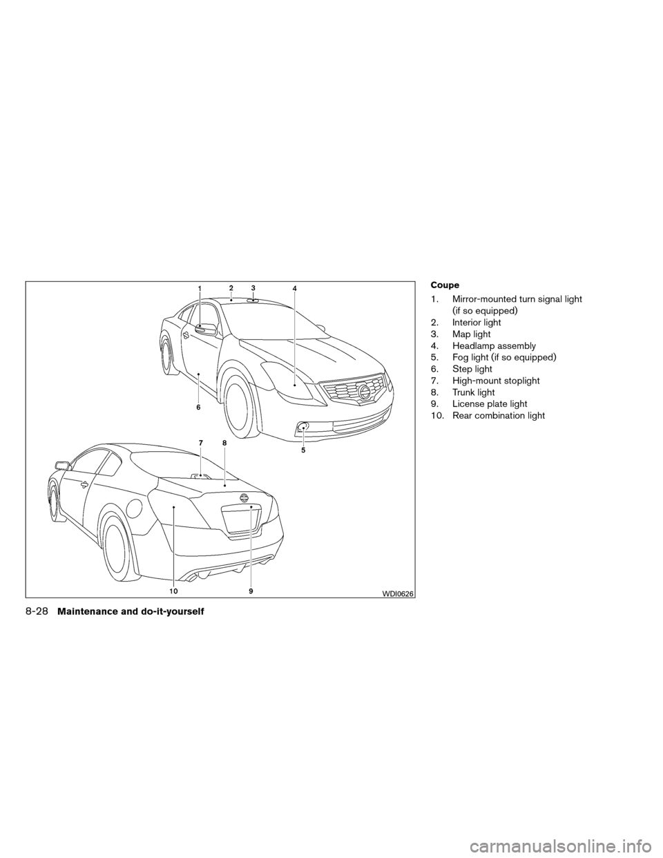
Coupe
1. Mirror-mounted turn signal light(if so equipped)
2. Interior light
3. Map light
4. Headlamp assembly
5. Fog light (if so equipped)
6. Step light
7. High-mount stoplight
8. Trunk light
9. License plate light
10. Rear combination light
WDI0626
8-28Maintenance and do-it-yourself
Page 360 of 414
Replacement procedures
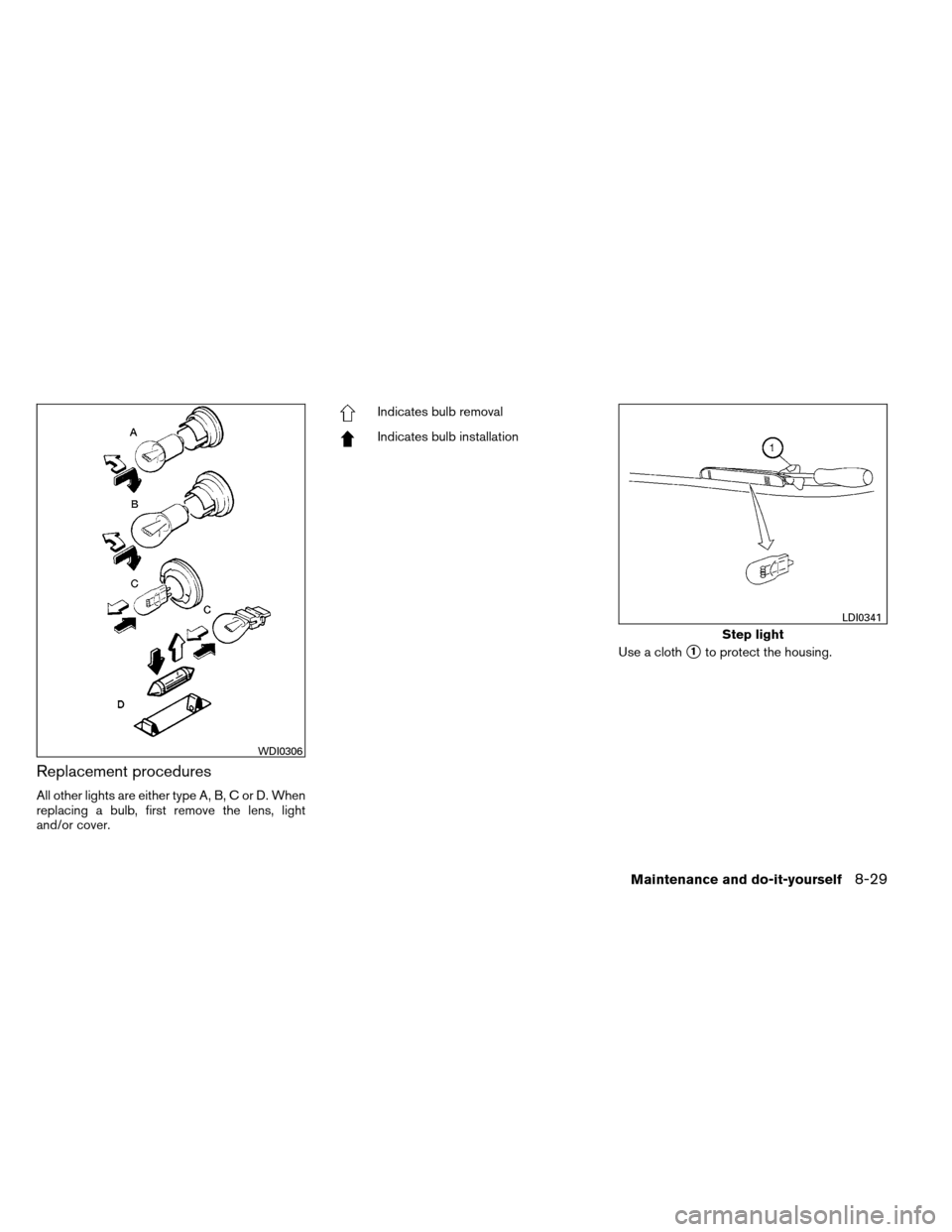
All other lights are either type A, B, C or D. When
replacing a bulb, first remove the lens, light
and/or cover.
Indicates bulb removal
Indicates bulb installationUse a cloth
�1to protect the housing.
WDI0306
Step light
LDI0341
Maintenance and do-it-yourself8-29
Page 361 of 414
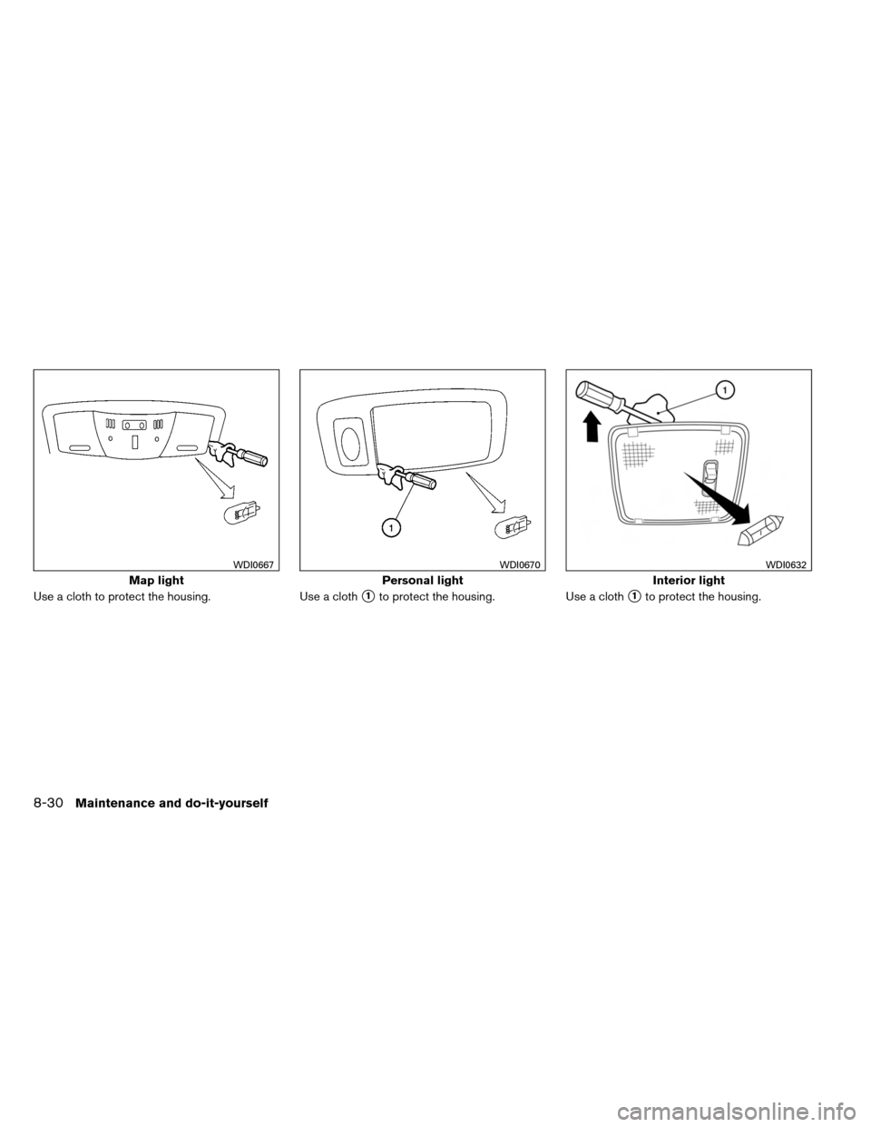
Use a cloth to protect the housing.Use a cloth�1to protect the housing.Use a cloth�1to protect the housing.
Map light
WDI0667
Personal light
WDI0670
Interior light
WDI0632
8-30Maintenance and do-it-yourself
Page 362 of 414
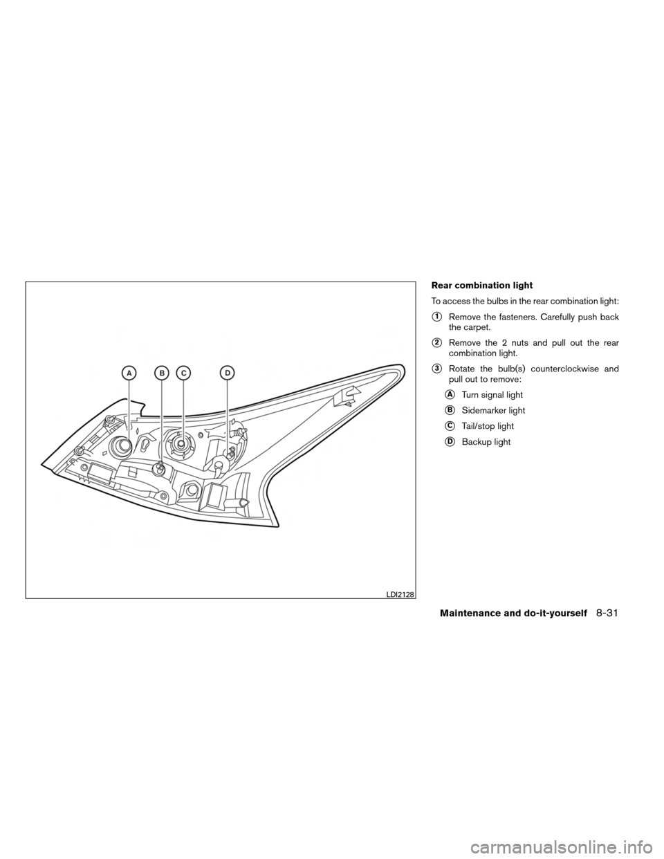
Rear combination light
To access the bulbs in the rear combination light:
�1Remove the fasteners. Carefully push back
the carpet.
�2Remove the 2 nuts and pull out the rear
combination light.
�3Rotate the bulb(s) counterclockwise and
pull out to remove:
�ATurn signal light
�BSidemarker light
�CTail/stop light
�DBackup light
LDI2128
Maintenance and do-it-yourself8-31
Page 363 of 414
CAUTION
Never force the covers into place because
the hinge pins can be damaged. Follow
the removal and installation instructions
to prevent inoperability of the covers.
REMOVING COVERS FROM REAR
PARCEL SHELF
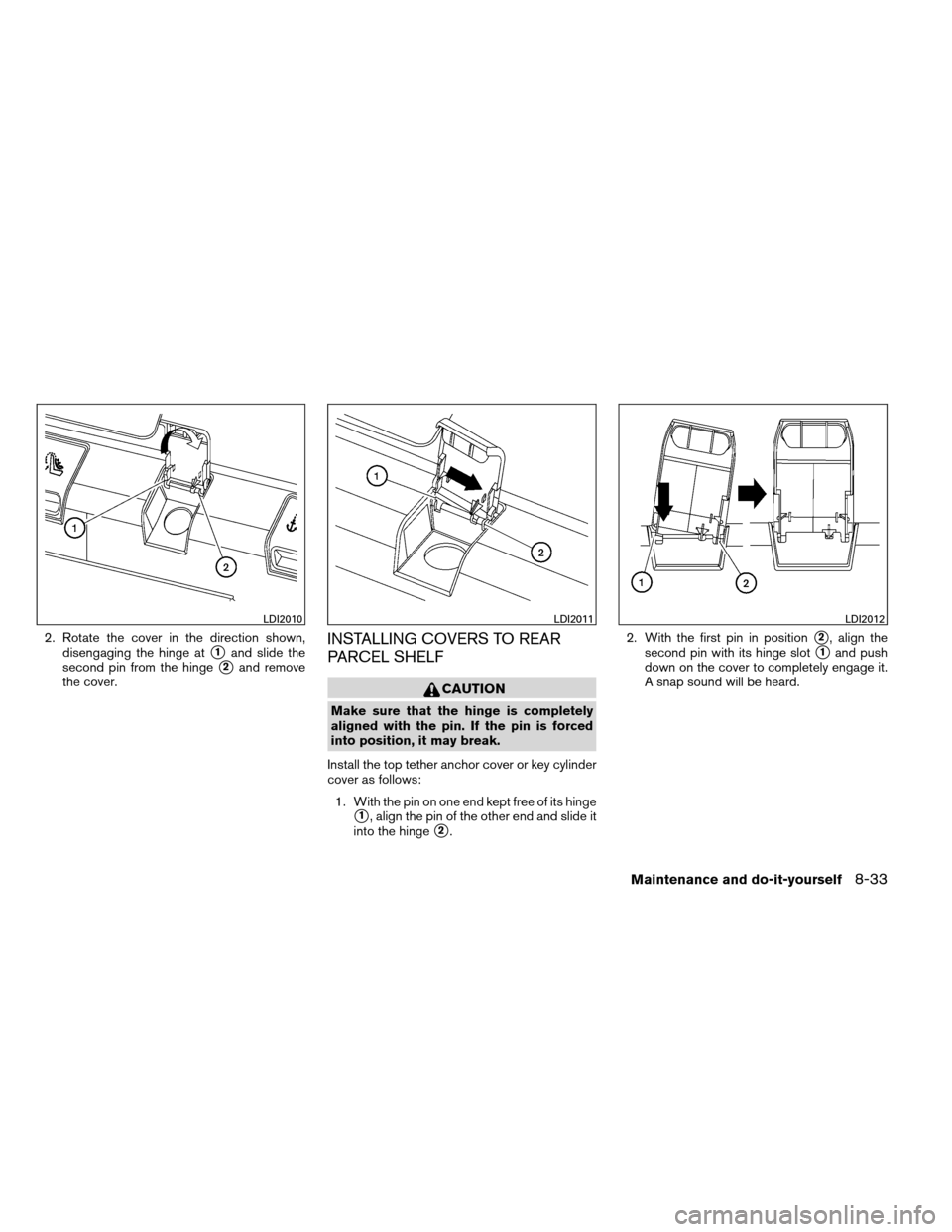
Remove the top tether anchor cover or key cylin-
der cover as follows:1. Lift the cover to the full open position.
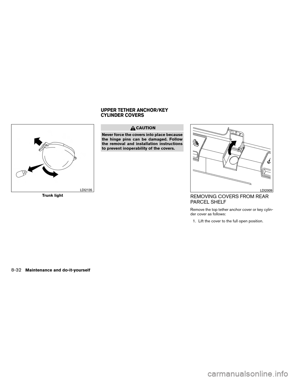
Trunk light
LDI2135LDI2009
UPPER TETHER ANCHOR/KEY
CYLINDER COVERS
8-32Maintenance and do-it-yourself
Page 364 of 414
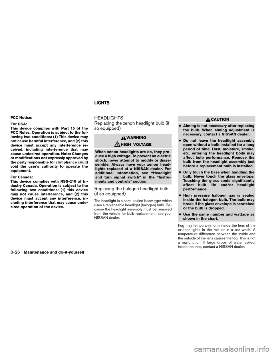
2. Rotate the cover in the direction shown,disengaging the hinge at
�1and slide the
second pin from the hinge
�2and remove
the cover.
INSTALLING COVERS TO REAR
PARCEL SHELF
CAUTION
Make sure that the hinge is completely
aligned with the pin. If the pin is forced
into position, it may break.
Install the top tether anchor cover or key cylinder
cover as follows: 1. With the pin on one end kept free of its hinge
�1, align the pin of the other end and slide it
into the hinge
�2. 2. With the first pin in position
�2, align the
second pin with its hinge slot
�1and push
down on the cover to completely engage it.
A snap sound will be heard.
LDI2010LDI2011LDI2012
Maintenance and do-it-yourself8-33