Page 414 of 706

5
Comfort controls
Vents. . . . . . . . . . . . . . . . . . . . . . . . . . . . . . . . . . . .5- 2
Manual air conditioning with MAX A/C mode
(if so equipped) . . . . . . . . . . . . . . . . . . . . . . . . . .5- 6
Manual air conditioning without MAX A/C mode
(if so equipped) . . . . . . . . . . . . . . . . . . . . . . . . . .5- 16
Automatic air conditioning with Fahrenheit scale
(if so equipped) . . . . . . . . . . . . . . . . . . . . . . . . . .5- 25
Automatic air conditioning with Celsius scale
(if so equipped) . . . . . . . . . . . . . . . . . . . . . . . . . .5- 35
Important air conditioning operating tips . . . . . . .5- 45
Air purifier . . . . . . . . . . . . . . . . . . . . . . . . . . . . . . .5- 46
AM/FM electronically tuned radio with CD player
(RBDS and MP3 compatible)
(if so equipped) . . . . . . . . . . . . . . . . . . . . . . . . . .5- 46
AM/FM electronically tuned radio with 6 CD
autochanger (RBDS and MP3 compatible)
(if so equipped) . . . . . . . . . . . . . . . . . . . . . . . . . .5- 74
To play tracks from USB device
(if so equipped) . . . . . . . . . . . . . . . . . . . . . . . . . .5-104
To play tracks from a Bluetooth® device
(vehicles with Bluetooth® 2.0 interface) . . . . . .5-121To use the external audio input function
(if so equipped) . . . . . . . . . . . . . . . . . . . . . . . . . 5- 125
Steering wheel audio remote control switch
(if so equipped) . . . . . . . . . . . . . . . . . . . . . . . . . 5- 127
Error codes . . . . . . . . . . . . . . . . . . . . . . . . . . . . . . 5- 130
Error codes (SIRIUS Satellite Radio)
(if so equipped) . . . . . . . . . . . . . . . . . . . . . . . . . 5- 132
Error codes (iPod) . . . . . . . . . . . . . . . . . . . . . . . . . 5- 134
Error codes (USB memory device) . . . . . . . . . . . . 5- 136
Handling of compact discs (CD) . . . . . . . . . . . . . . 5- 138
Antenna . . . . . . . . . . . . . . . . . . . . . . . . . . . . . . . . . 5- 141
Digital clock (if so equipped) . . . . . . . . . . . . . . . . 5- 141
General information about your radio . . . . . . . . . . 5- 142
BK0151000US.book 1 ページ 2012年3月29日 木曜日 午後6時8分
Page 540 of 706
Comfort controls
5-127
5 Steering wheel audio remote control switch
(if so equipped)
N00714800455
The remote control switch is located on the left side of the
steering wheel.
The switch can be operated when the ignition switch is in
either the “ON” or “ACC” position.
NOTE�Do not press multiple buttons at the same time when using
the steering wheel audio remote control switch.To turn on the powerPress the power switch (3) to turn on the power. When the
power is turned on, the last mode used before turning off is dis-
played. To turn off the power, press and hold down the power
switch (3) for about 2 seconds until you hear a beep.
Ty p e 1
1- Volume up button
2- Volume down button
3- Power switch/Mode selector button
4- Seek up/Track up/File up/Fast-forward button
5- Seek down/Track down/File down/Fast-reverse buttonTy p e 2
BK0151000US.book 127 ページ 2012年3月29日 木曜日 午後6時8分
Page 559 of 706

6-2 For emergencies
6If the vehicle breaks down
N00836300204
If your vehicle breaks down on the road, move to the shoulder
and turn on the hazard warning flashers. If there is no shoulder,
or the shoulder is not safe, drive in the right lane slowly, with
the hazard lights flashing, until you come to a safe stopping
place. Keep the flashers flashing. If the engine stops/fails If the engine stops, there will be no power assist to the steering
and brakes, making these difficult to use.
�The brake booster will not work, so the brakes will not
grip well. The brake pedal will be harder to press than
usual.
�Since there is no power steering assist, the steering wheel
will be hard to turn. When the engine fails at the intersection Get help from your passengers, bystanders, etc. to push the
vehicle and move it to a safe zone.
Jump-starting the engine
N00836400654
If the engine cannot be started because the battery is weak or
dead, you can start it with the battery from another vehicle
using jumper cables.
1. Take off any metal jewelry such as watch bands or brace-
lets that might make an accidental electrical contact.
2. Position the vehicles close enough together so that the
jumper cables can reach, but be sure the vehicles aren’t
touching each other.
WA R N I N G
!�When using jumper cables to start a vehicle, follow
the procedures and be very cautious.
CAUTION
!�Do not try to start your vehicle by pushing or tow-
ing. Vehicles equipped with continuously variable
transmission (CVT) or Twin Clutch SST cannot be
started this way. Pushing or towing a vehicle that
has a manual transaxle may overheat and damage
the catalytic converter. Also, there is more risk of an
accident when a vehicle is being pushed or towed.
CAUTION
!�Check the other vehicle. It must have a 12-volt bat-
tery. If the other system isn’t 12-volt, both systems
can be damaged.
BK0151000US.book 2 ページ 2012年3月29日 木曜日 午後6時8分
Page 564 of 706
For emergencies
6-7
6 Tools and jack
N00836600324
StorageThe tools and jack are stowed in the luggage compartment.
Tools
N00832600124
1- Tools
2- Jack
1- Tool bag
2- Bar
3- Wheel nut wrench
BK0151000US.book 7 ページ 2012年3月29日 木曜日 午後6時8分
Page 566 of 706

For emergencies
6-9
6
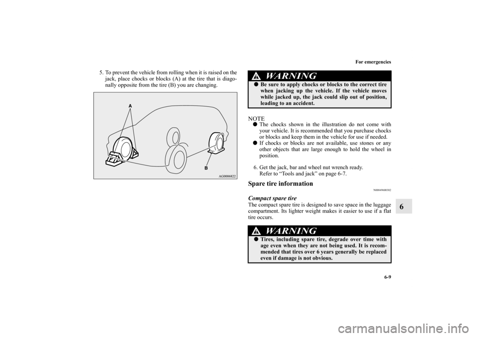
5. To prevent the vehicle from rolling when it is raised on the
jack, place chocks or blocks (A) at the tire that is diago-
nally opposite from the tire (B) you are changing.
NOTE�The chocks shown in the illustration do not come with
your vehicle. It is recommended that you purchase chocks
or blocks and keep them in the vehicle for use if needed.
�If chocks or blocks are not available, use stones or any
other objects that are large enough to hold the wheel in
position.
6. Get the jack, bar and wheel nut wrench ready.
Refer to “Tools and jack” on page 6-7.Spare tire information
N00849600302
Compact spare tireThe compact spare tire is designed to save space in the luggage
compartment. Its lighter weight makes it easier to use if a flat
tire occurs.
WA R N I N G
!�Be sure to apply chocks or blocks to the correct tire
when jacking up the vehicle. If the vehicle moves
while jacked up, the jack could slip out of position,
leading to an accident.
WA R N I N G
!�Tires, including spare tire, degrade over time with
age even when they are not being used. It is recom-
mended that tires over 6 years generally be replaced
even if damage is not obvious.
BK0151000US.book 9 ページ 2012年3月29日 木曜日 午後6時8分
Page 567 of 706

6-10 For emergencies
6
CAUTION
!�While the compact spare tire is stowed, the inflation
pressure should be checked at least once a month to
assure that it remains at the recommended inflation
pressure. See the tire and loading information plac-
ard attached to the driver’s door sill.
Refer to “Tire and loading information placard” on
page 9-4.�Driving with an improperly inflated tire can cause
an accident. If you have no choice but to drive with
an under-inflated tire, keep your speed down and
avoid sudden steering or braking, if possible. Inflate
the tire to the correct pressure as soon as possible.
Refer to “Tire inflation pressures” on page 7-32.�The compact spare tire should be used only tempo-
rarily. While the compact spare tire is being used,
the tire pressure monitoring system will not function
properly. Have the tire replaced or repaired at an
authorized Mitsubishi Motors dealer or a repair
facility of your choice as soon as possible.�You can use the same wheel nuts on the compact
spare tire wheel. �Do not go over 50 mph (80 km/h) when driving with
the compact spare tire.�Avoid fast starting and braking when driving with
the compact spare tire. �Do not drive through automatic car washes and over
obstacles that could possibly damage the underside
of your vehicle. Because the compact spare tire is
smaller than the original tire, there is less clearance
between the ground and your vehicle.
�Because the compact spare tire is designed only for
your vehicle, do not use it on any other vehicle. �Do not put the compact spare tire on a different
wheel, and do not put standard tires, snow tires,
wheel covers or trim rings on the compact spare
wheel. Otherwise, you could damage these parts or
other parts on your vehicle.�Do not use snow chain with your compact spare tire.
Using a chain could cause damage to your vehicle
and loss of the chains.
CAUTION
!
BK0151000US.book 10 ページ 2012年3月29日 木曜日 午後6時8分
Page 569 of 706
6-12 For emergencies
6
To change a tire
N00849800434
1. On vehicles equipped with wheel covers, first remove the
covers (refer to “Wheel covers” on page 6-19). Then
loosen the wheel nuts with the wheel nut wrench. Do not
remove the wheel nuts yet.2. Place the jack under one of the jacking points (A) shown
in the illustration. Use the jacking point closest to the tire
you wish to change.
WA R N I N G
!�Set the jack only at the positions shown here. If the
jack is set at a wrong position, it could dent your
vehicle or the jack might fall over and cause per-
sonal injury. �Do not use the jack on a tilted or soft surface.
Otherwise, the jack might slip and cause personal
injury. Always use the jack on a flat, hard surface.
Before setting the jack, make sure there are no sand
or pebbles under the jack base.
BK0151000US.book 12 ページ 2012年3月29日 木曜日 午後6時8分
Page 570 of 706
For emergencies
6-13
6
3. Rotate the jack by hand until the flange portion (B) fits in
the groove (C) at the top of the jack. 4. Insert the bar (D) into the wheel nut wrench (E). Then put
the end of the bar into the shaft’s jack end, as shown in the
illustration.
Slowly rotate the wheel nut wrench until the tire is raised
slightly off the ground surface.
WA R N I N G
!�Stop jacking up the vehicle as soon as the tire is
raised off the ground. It is dangerous to raise the
vehicle any higher. �Never get under the vehicle or put any portion of
your body under the vehicle while it is supported by
the jack. �Do not bump the raised vehicle or leave it sitting on
the jack for a long time. Both are very dangerous. �Do not use a jack except the one that came with your
vehicle.
BK0151000US.book 13 ページ 2012年3月29日 木曜日 午後6時8分