Page 330 of 706
Features and controls
3-237
3
�It is possible to modify functions as follows:
• The headlights can be set to come on in the low beam
setting.
• The welcome light function can be deactivated.
For details, consult a Mitsubishi Motors dealer.
On vehicles equipped with a Mitsubishi Multi-Communi-
cation System, screen operations can be used to make the
adjustment.
Refer to the separate owner’s manual for details.
Coming home light
N00547300096
This function turns on the headlights in the low beam setting
for about 30 seconds after the ignition switch is turned to the
“LOCK” position.
1. Turn the combination headlights and dimmer switch to the
“OFF” or “AUTO” position (for vehicles equipped with
the automatic light control).
2. Turn the ignition switch to the “LOCK” position. Also, if
a key was used to start the engine, remove the key from
the ignition switch.
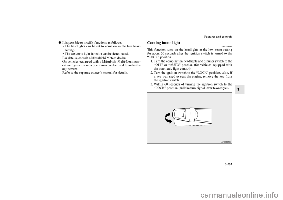
3. Within 60 seconds of turning the ignition switch to the
“LOCK” position, pull the turn signal lever toward you.
BK0151000US.book 237 ページ 2012年3月29日 木曜日 午後6時8分
Page 331 of 706
3-238 Features and controls
3
4. The headlights will come on in the low beam setting for
about 30 seconds. After the headlights go off, the head-
lights can be turned on again in the low beam setting for
about 30 seconds by pulling the turn signal lever toward
you within 60 seconds of turning the ignition switch to the
“LOCK” position. To turn on the headlights again after 60
seconds of turning the ignition switch to the “LOCK”
position, repeat the process from step 1.NOTE�While the coming home light function is operating, per-
form one of the following operations to cancel the func-
tion.
• Pull the turn signal lever toward you.
• Turn the combination headlights and dimmer switch to
the “ ” or “ ” position.
• Turn the ignition switch to the “ON” position.
�It is possible to modify functions as follows:
• The time that the headlights remain on can be changed.
• The coming home light function can be deactivated.
For details, consult a Mitsubishi Motors dealer.
On vehicles equipped with a Mitsubishi Multi-Communi-
cation System, screen operations can be used to make the
adjustment.
Refer to the separate owner’s manual for details.
Headlight leveling switch
(if so equipped)
N00537100062
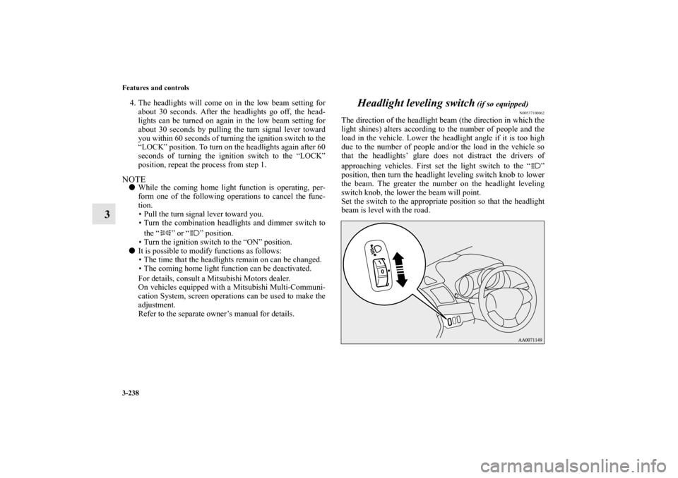
The direction of the headlight beam (the direction in which the
light shines) alters according to the number of people and the
load in the vehicle. Lower the headlight angle if it is too high
due to the number of people and/or the load in the vehicle so
that the headlights’ glare does not distract the drivers of
approaching vehicles. First set the light switch to the “ ”
position, then turn the headlight leveling switch knob to lower
the beam. The greater the number on the headlight leveling
switch knob, the lower the beam will point.
Set the switch to the appropriate position so that the headlight
beam is level with the road.
BK0151000US.book 238 ページ 2012年3月29日 木曜日 午後6時8分
Page 341 of 706
3-248 Features and controls
3
Windshield washer
N00504600269
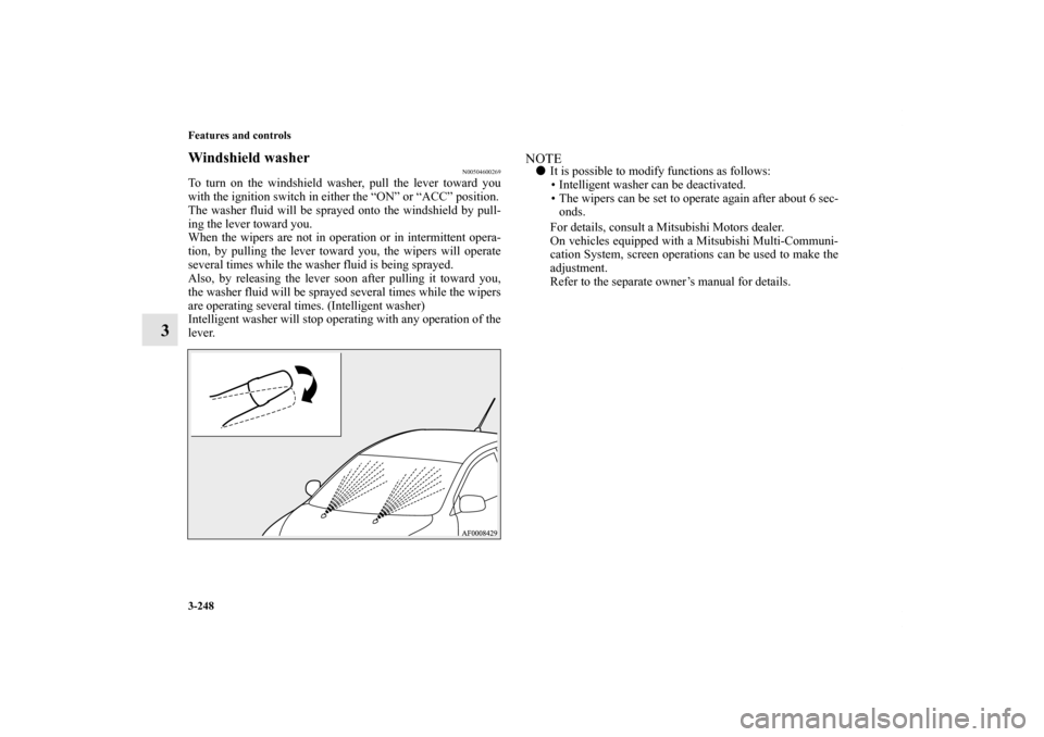
To turn on the windshield washer, pull the lever toward you
with the ignition switch in either the “ON” or “ACC” position.
The washer fluid will be sprayed onto the windshield by pull-
ing the lever toward you.
When the wipers are not in operation or in intermittent opera-
tion, by pulling the lever toward you, the wipers will operate
several times while the washer fluid is being sprayed.
Also, by releasing the lever soon after pulling it toward you,
the washer fluid will be sprayed several times while the wipers
are operating several times. (Intelligent washer)
Intelligent washer will stop operating with any operation of the
lever.
NOTE�It is possible to modify functions as follows:
• Intelligent washer can be deactivated.
• The wipers can be set to operate again after about 6 sec-
onds.
For details, consult a Mitsubishi Motors dealer.
On vehicles equipped with a Mitsubishi Multi-Communi-
cation System, screen operations can be used to make the
adjustment.
Refer to the separate owner’s manual for details.
BK0151000US.book 248 ページ 2012年3月29日 木曜日 午後6時8分
Page 396 of 706
Features and controls
3-303
3
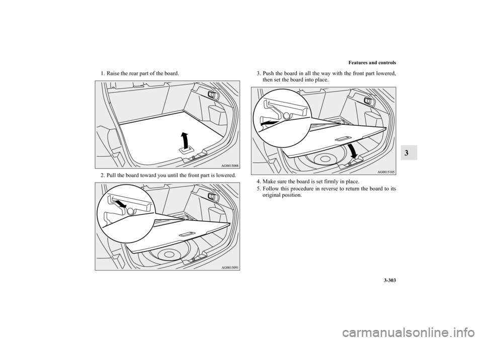
1. Raise the rear part of the board.
2. Pull the board toward you until the front part is lowered.3. Push the board in all the way with the front part lowered,
then set the board into place.
4. Make sure the board is set firmly in place.
5. Follow this procedure in reverse to return the board to its
original position.
BK0151000US.book 303 ページ 2012年3月29日 木曜日 午後6時8分
Page 398 of 706
4
Driving safety
Fuel economy . . . . . . . . . . . . . . . . . . . . . . . . . . . . .4- 2
Driving, alcohol and drugs. . . . . . . . . . . . . . . . . . .4- 2
Floor mat . . . . . . . . . . . . . . . . . . . . . . . . . . . . . . . .4- 3
Vehicle preparation before driving. . . . . . . . . . . . .4- 5
Safe driving techniques . . . . . . . . . . . . . . . . . . . . .4- 6
Driving during cold weather . . . . . . . . . . . . . . . . .4- 6
Braking. . . . . . . . . . . . . . . . . . . . . . . . . . . . . . . . . .4- 7
Parking . . . . . . . . . . . . . . . . . . . . . . . . . . . . . . . . . .4- 8
Loading information . . . . . . . . . . . . . . . . . . . . . . .4- 9
Cargo loads . . . . . . . . . . . . . . . . . . . . . . . . . . . . . .4- 13
Trailer towing. . . . . . . . . . . . . . . . . . . . . . . . . . . . .4- 16
BK0151000US.book 1 ページ 2012年3月29日 木曜日 午後6時8分
Page 405 of 706
4-8 Driving safety
4Parking
N00629600261
Parking on a hillWhen parking on a hill, set the parking brake, and turn the
front wheels toward the curb on a downhill, or away from the
curb on an uphill.
If necessary, apply chocks to wheels.For vehicles equipped with manual transaxlePlace the gearshift lever into the “R” (Reverse) position when
parking on a downhill slope, into the 1st position when parking
on an uphill slope.For vehicles equipped with continuously variable trans-
mission (CVT) or Twin Clutch SSTBe sure that the parking brake is firmly set when parked and
that the selector lever (CVT) or gearshift lever (Twin Clutch
SST) is in the “P” (PARK) position.
When parking on a hill, it is important to set the parking brake
before moving the selector lever (CVT) or gearshift lever
(Twin Clutch SST) to the “P” (PARK) position. This prevents
loading the parking brake against the transaxle. When this hap-
pens, it is difficult to move the selector lever (CVT) or gear-
shift lever (Twin Clutch SST) out of the “P” (PARK) position.
Parking with the engine runningNever leave the engine running while you take a short
sleep/rest. Also, never leave the engine running in a closed or
poorly ventilated place.Where you parkYour front bumper can be damaged if you scrape it over curbs
or parking stop blocks. Be careful when traveling up or down
steep slopes where your bumper can scrape the road.When leaving the vehicleWhen leaving the vehicle unattended, always carry the key and
lock all doors and the rear hatch.
Always try to park your vehicle in a well lit area.
WA R N I N G
!�Leaving the engine running risks injury or death
from accidentally moving the gearshift lever (man-
ual transaxle or Twin Clutch SST) or the selector
lever (CVT) or from the accumulation of toxic
exhaust fumes in the passenger compartment.
WA R N I N G
!�Do not park your vehicle in areas where combustible
materials such as dry grass or leaves can come in
contact with a hot exhaust, since a fire could occur.
BK0151000US.book 8 ページ 2012年3月29日 木曜日 午後6時8分
Page 408 of 706
Driving safety
4-11
4
Ty p e 2
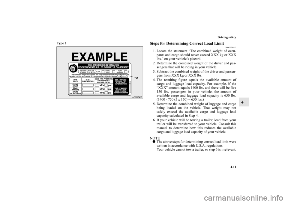
Steps for Determining Correct Load Limit
N00630200182
1. Locate the statement “The combined weight of occu-
pants and cargo should never exceed XXX kg or XXX
lbs.” on your vehicle’s placard.
2. Determine the combined weight of the driver and pas-
sengers that will be riding in your vehicle.
3. Subtract the combined weight of the driver and passen-
gers from XXX kg or XXX lbs.
4. The resulting figure equals the available amount of
cargo and luggage load capacity. For example, if the
“XXX” amount equals 1400 lbs. and there will be five
150 lbs. passengers in your vehicle, the amount of
available cargo and luggage load capacity is 650 lbs.
(1400 - 750 (5 x 150) = 650 lbs.)
5. Determine the combined weight of luggage and cargo
being loaded on the vehicle. That weight may not
safely exceed the available cargo and luggage load
capacity calculated in Step 4.
6. If your vehicle will be towing a trailer, load from your
trailer will be transferred to your vehicle. Consult this
manual to determine how this reduces the available
cargo and luggage load capacity of your vehicle.NOTE�The above steps for determining correct load limit were
written in accordance with U.S.A. regulations.
Your vehicle cannot tow a trailer, so step 6 is irrelevant.
BK0151000US.book 11 ページ 2012年3月29日 木曜日 午後6時8分
Page 412 of 706
Driving safety
4-15
4
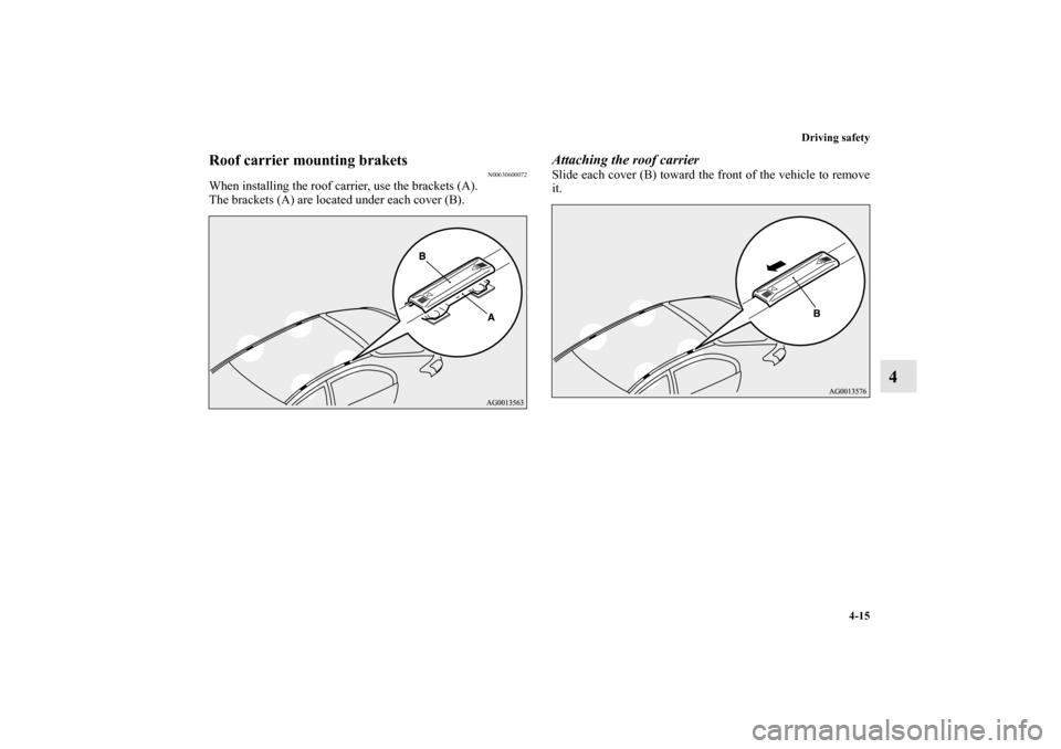
Roof carrier mounting brakets
N00630600072
When installing the roof carrier, use the brackets (A).
The brackets (A) are located under each cover (B).
Attaching the roof carrierSlide each cover (B) toward the front of the vehicle to remove
it.
BK0151000US.book 15 ページ 2012年3月29日 木曜日 午後6時8分