Page 317 of 706

3-224 Features and controls
3Indicators
N00519900127
Turn signal indicators/Hazard warning lights
N00520000229
The arrows will flash in time with the corresponding exterior
turn signals when the turn signal lever is used.
Both arrows will flash when the hazard warning flasher switch
is pressed.NOTE�If the indicator flashes faster than usual or if the indicator
stays on without flashing, check for a malfunctioning turn
signal light bulb or turn signal connection.High beam indicator
N00520100086
A blue light comes on when the headlights are on high beam.Front fog light indicator
N00520200218
This indicator comes on while the front fog lights are on.Position indicator
N00551300026
This indicator light illuminates while the position lights are on.
Warning lights
N00520300147
Brake warning light
N00520400366
When the ignition switch is turned to the “ON” position, this
indicator normally comes on and goes out a few seconds later.
A warning is also displayed in the multi-information display.
The warning light also illuminates after starting the engine
under the following conditions:
�When the parking brake is still applied.
�When the brake fluid level is low.
�When the brake system circuit is not working properly.
Before driving, be sure that the parking brake is fully released
and brake warning light is off.
CAUTION
!�If the brake warning light and the anti-lock braking
system warning light are illuminated at the same
time, the braking force distribution function will not
operate, so the vehicle may be destabilized during
sudden braking under the following conditions.
• When the brake warning light does not go out even
when the parking brake is released.
• When the brake warning light stays on while driv-
ing.
• If the above occurs, avoid sudden braking and
high-speed driving. Park the vehicle in a safe
place, and contact an authorized Mitsubishi
Motors dealer or a repair facility of your choice as
soon as possible.
BK0151000US.book 224 ページ 2012年3月29日 木曜日 午後6時8分
Page 333 of 706

3-240 Features and controls
3
NOTE�A light in the instrument panel flashes to show when the
front and rear turn signal lights are working properly.
If this light flashes faster than usual, check for a burned
out light bulb or malfunctioning connection.
If the panel light does not come on when the lever is
moved, check for a blown fuse or a burned out bulb in the
panel.
Have the vehicle inspected by an authorized Mitsubishi
Motors dealer or a repair facility of your choice.
�It is possible to modify functions as follows:
• Deactivate the turn signal light 3-flash function for lane
changes.
• Adjust the time required to operate the lever for the 3-
flash function.
See your authorized Mitsubishi Motors dealer for details.
For vehicles equipped with the Mitsubishi Multi-Commu-
nication System, adjustments can be made using screen
operations. For further details, refer to the separate
owner’s manual.
Hazard warning flasher switch
N00522700233
If you press the flasher switch, the front and rear turn signals
will flash intermittently, and so will the hazard warning lights.
This is an emergency warning system and should not be used
when the vehicle is in motion, except for emergencies.
If you need to leave your vehicle, the flashers will keep work-
ing after the ignition switch is turned off. NOTE�If you keep the flashers on for several hours with the
engine turned off, the battery will run down.
BK0151000US.book 240 ページ 2012年3月29日 木曜日 午後6時8分
Page 638 of 706
![MITSUBISHI LANCER SPORTBACK 2013 8.G Owners Manual Vehicle care and maintenance
7-57
7
[For vehicles without high intensity discharge headlights] [For vehicles equipped with high intensity discharge head-
lights]
Description
Wattage
ANSI Trade
No. or](/manual-img/19/7504/w960_7504-637.png "MITSUBISHI LANCER SPORTBACK 2013 8.G Owners Manual Vehicle care and maintenance
7-57
7
[For vehicles without high intensity discharge headlights] [For vehicles equipped with high intensity discharge head-
lights]
Description
Wattage
ANSI Trade
No. or")
Vehicle care and maintenance
7-57
7
[For vehicles without high intensity discharge headlights] [For vehicles equipped with high intensity discharge head-
lights]
Description
Wattage
ANSI Trade
No. or Bulb
type
1-Front turn signal
light21 W WY21W
2- Headlight, high beam 60 W9005
HB3
3-Headlight, low beam
(Halogen bulb)51 W9006
HB4
4- Front fog light 55 W H11
5-Front side-marker
and parking light5 W WY5W
6- Side turn signal light 5 W —
Description
Wattage or Candle
power
ANSI Trade
No. or Bulb
type
1-Front turn signal
light21 W WY21W
2-Daytime running
light27 W
32 cp1156
3-Headlight, low/high
beam (Discharge
bulb)35 W —
4- Front fog light 55 W H11
5-Front side-marker
and parking light5 W WY5W
6- Side turn signal light 5 W —
WA R N I N G
!�Check with an authorized Mitsubishi Motors dealer
or a repair facility of your choice when it is neces-
sary to repair a discharge headlight or to replace the
bulb.
The power circuit, bulb and electrodes generate high
voltages that may cause a severe electrical shock.
BK0151000US.book 57 ページ 2012年3月29日 木曜日 午後6時8分
Page 639 of 706
7-58 Vehicle care and maintenance
7
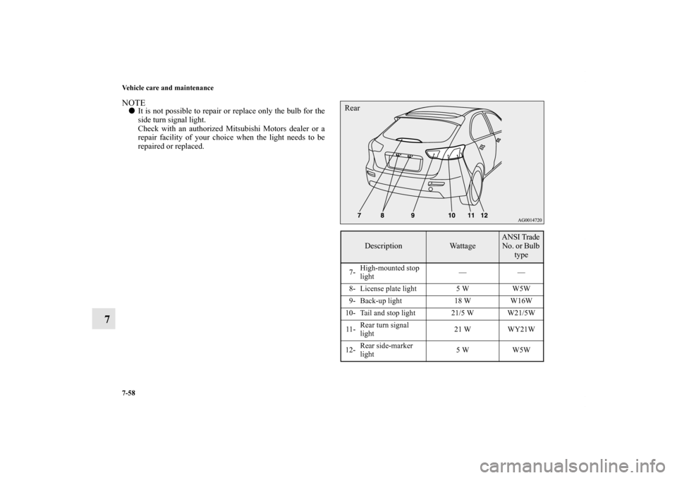
NOTE�It is not possible to repair or replace only the bulb for the
side turn signal light.
Check with an authorized Mitsubishi Motors dealer or a
repair facility of your choice when the light needs to be
repaired or replaced.
Description
Wattage
ANSI Trade
No. or Bulb
type
7-High-mounted stop
light——
8- License plate light 5 W W5W
9- Back-up light 18 W W16W
10- Tail and stop light 21/5 W W21/5W
11-Rear turn signal
light21 W WY21W
12-Rear side-marker
light5 W W5WRear
BK0151000US.book 58 ページ 2012年3月29日 木曜日 午後6時8分
Page 652 of 706
Vehicle care and maintenance
7-71
7
5. To install the bulb, perform the removal steps in reverse.
Front turn signal lights
N00943400325
1. Remove the clips (A) and clips (B), then remove the duct
(C) and the upper cover (D).Except for vehicles with turbocharger
BK0151000US.book 71 ページ 2012年3月29日 木曜日 午後6時8分
Page 662 of 706
Vehicle care and maintenance
7-81
7
Rear combination lights
N00943700429
Tail and stop lights, rear turn signal lights and rear
side-marker lights1. Insert a screwdriver at the edge of the cover and pry gen-
tly to remove the cover. NOTE�Wrap a cloth around the tip of the screwdriver to keep
from scratching the cover.2. Remove the socket and bulb assemblies by turning them
counterclockwise.
A- Rear side-marker light
B- Rear turn signal light
C- Tail and stop light
BK0151000US.book 81 ページ 2012年3月29日 木曜日 午後6時8分
Page 663 of 706
7-82 Vehicle care and maintenance
7
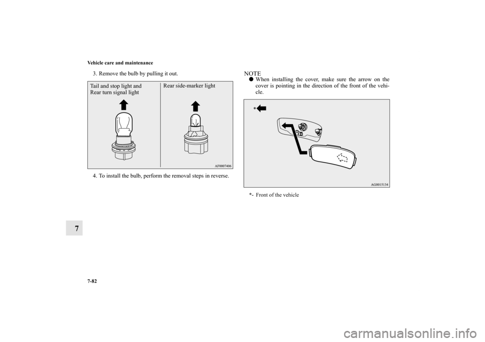
3. Remove the bulb by pulling it out.
4. To install the bulb, perform the removal steps in reverse.
NOTE�When installing the cover, make sure the arrow on the
cover is pointing in the direction of the front of the vehi-
cle.
Tail and stop light and
Rear turn signal lightRear side-marker light
*- Front of the vehicle
BK0151000US.book 82 ページ 2012年3月29日 木曜日 午後6時8分
Page 700 of 706
 3-4
,3-42
Emission-control system m")
Alphabetical index
3
Dual height adjustable cargo floor board 3-302
E
Electric rear window defogger switch 3-251
Electronic immobilizer (Anti-theft starting system) 3-4
,3-42
Emission-control system maintenance 7-41
Engine
Compartment 7-7
Coolant 7-11
,9-10
Hood 7-4
Oil and oil filter 7-8
,9-10
Overheating 6-5
Serial number 9-4
Specifications 9-8
Engine coolant temperature display 3-187
Exhaust system 7-44
External audio input connector 5-125
F
Filling the fuel tank 1-4
Floor console box 3-298
Floor mat 4-3
Fluid 9-10
AWC control fluid 7-19
,9-10
Brake fluid 7-21
,9-10
Clutch fluid 7-21,9-10
Continuously variable transmission (CVT) fluid 7-17
,9-10
Engine coolant 7-11
,9-10
Power steering fluid 7-22
,9-10Twin Clutch SST fluid 7-18
,9-10
Washer fluid 9-10
Fluid capacities and lubricants 9-10
Fog lights
Bulb capacity 7-56
Indicator 3-224
Replacement 7-73
,7-77
Switch 3-241
Free-hand advanced security transmitter (F.A.S.T.-key) 3-16
Front console boxes 3-297
Front console tray 3-296
Front seats 2-3
Front side-marker and parking light
Bulb capacity 7-56
Replacement 7-67,7-69
Front turn signal lights
Bulb capacity 7-56
Replacement 7-71
Fuel
Fuel economy 4-2
Fuel hoses 7-42
Modification/alterations to the electrical or fuel systems 1-9
Tank capacity 1-5,9-10
Fuel selection 1-2
Fuses 7-46
Fusible links 7-46
G
General maintenance 7-43
BK0151000US.book 3 ページ 2012年3月29日 木曜日 午後6時8分
 and clips (B), then remove the duct
(C)")