Page 558 of 722
Comfort controls
5-139
5 Error codes (SIRIUS Satellite Radio)
(if so equipped)
N00760300053
If an error code (1) appears in the display, take action in accordance with the table below.
Error display
Problem
Description
Repair
ANTENNA ↔ ERROR Antenna errorThe antenna may be faulty, not securely
connected, or open-circuited.Take the vehicle to your authorized
Mitsubishi Motors dealer or a repair
facility of your choice.
ACQUIRING Cannot pick up signal. The signal is too weak to be received.Move to a place where the signal is
easy to receive.
CALL ↔ 888-539-SIRIUS Unauthorized channelContract does not include reception of this
channel.Contact SIRIUS Satellite Radio and
obtain a contract.
NO CHANNELThere is no selectable
channel.There is no selectable channel. Cancel SKIP settings.
BK0150800US.book 139 ページ 2012年3月29日 木曜日 午後2時38分
Page 567 of 722
5-148 Comfort controls
5Antenna
N00734200426
Roof antenna (except for vehicles with SIRIUS
satellite radio)To r e m o v eTurn the pole (A) counterclockwise.To i n s t a l lScrew the pole (A) clockwise into the base (B) until it is
securely retained.NOTE�Be sure to remove the roof antenna in the following cases:
• When using an automatic car wash
• When covering your vehicle with a car cover
• When driving into a structure that has a low ceiling
Roof antenna (for vehicles with SIRIUS satellite
radio)For securing the best satellite reception, the angle of the
antenna is fixed.
BK0150800US.book 148 ページ 2012年3月29日 木曜日 午後2時38分
Page 568 of 722
Comfort controls
5-149
5
To r e m o v eTurn the pole (A) counterclockwise.To i n s t a l lScrew the pole (A) clockwise into the base (B) until it is
securely retained.NOTE�Be sure to remove the roof antenna in the following cases:
• When entering a place with low clearance
• When using an automatic car wash
• When covering your vehicle with a car cover
Digital clock
(if so equipped)
N00755000094
The time is displayed when the ignition switch is in the “ON”
or “ACC” position.To set the time1. Press and hold the CLOCK button and the clock display
flashes.
2. Press the various buttons to adjust.H — “Hour” setting
Press this button to fast-forward the “hours”.
M — “Minutes” setting
Press this button to fast-forward the “minutes”.
CLOCK DISP H M :00
BK0150800US.book 149 ページ 2012年3月29日 木曜日 午後2時38分
Page 594 of 722
For emergencies
6-21
6
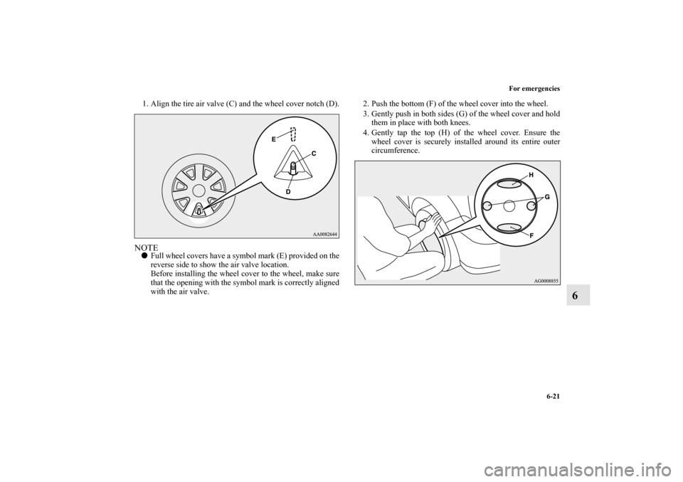
1. Align the tire air valve (C) and the wheel cover notch (D).NOTE�Full wheel covers have a symbol mark (E) provided on the
reverse side to show the air valve location.
Before installing the wheel cover to the wheel, make sure
that the opening with the symbol mark is correctly aligned
with the air valve.2. Push the bottom (F) of the wheel cover into the wheel.
3. Gently push in both sides (G) of the wheel cover and hold
them in place with both knees.
4. Gently tap the top (H) of the wheel cover. Ensure the
wheel cover is securely installed around its entire outer
circumference.
BK0150800US.book 21 ページ 2012年3月29日 木曜日 午後2時38分
Page 596 of 722
Place the gearshift lever in the “Neutral” position.
Turn the ign")
For emergencies
6-23
6
Towing the vehicle by a tow truck
Towing manual transaxle vehicles with rear wheels off
the ground (Type B)Place the gearshift lever in the “Neutral” position.
Turn the ignition switch to the “ACC” position and secure the
steering wheel in a straight-ahead position with a rope or tie-
down strap. Never place the ignition switch in the “LOCK”
position when towing.
CAUTION
!�This vehicle must not be towed by a tow truck using
sling lift type equipment (Type A) as illustrated.
Using a sling lift will damage the bumper and front
end.�Do not tow all-wheel drive vehicles with the front or
rear wheels on the ground (Type B or Type C) as
illustrated. This could result in the driving system
damage or vehicle may jump at the carriage.
If you tow all-wheel drive vehicles, use Type D or
Type E equipment.�Do not tow continuously variable transmission
(CVT) vehicles with the driving wheels on the
ground (Type B) as illustrated. If the vehicle is
towed like this, the continuously variable transmis-
sion (CVT) fluid may not reach all parts of the
transmission, thus damaging it.
If you tow CVT vehicles, use Type C, D or E equip-
ment.�If the manual transaxle is malfunctioning or dam-
aged, transport the vehicle with the driving wheels
on a carriage (Type C, D or E) as illustrated.
�[For front-wheel drive vehicle equipped with the
active stability control (ASC)]
If the vehicle is towed with the ignition switch in the
“ON” position and only the front wheels or only the
rear wheels raised off the ground, the ASC may
operate, resulting in an accident. When towing the
vehicle with only the front wheels or only the rear
wheels raised, keep the ignition switch in the
“LOCK” or “ACC” position.�[For vehicle equipped with the Electronically con-
trolled 4WD system]
Even in “2WD” mode, the vehicle cannot be towed
with the front or the rear wheels on the ground.
CAUTION
!
BK0150800US.book 23 ページ 2012年3月29日 木曜日 午後2時38分
Page 604 of 722
Vehicle care and maintenance
7-5
7
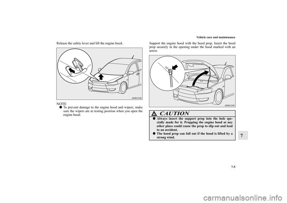
Release the safety lever and lift the engine hood. NOTE�To prevent damage to the engine hood and wipers, make
sure the wipers are at resting position when you open the
engine hood. Support the engine hood with the hood prop. Insert the hood
prop securely in the opening under the hood marked with an
arrow.
CAUTION
!�Always insert the support prop into the hole spe-
cially made for it. Propping the engine hood at any
other place could cause the prop to slip out and lead
to an accident. �The hood prop can fall out if the hood is lifted by a
strong wind.
BK0150800US.book 5 ページ 2012年3月29日 木曜日 午後2時38分
Page 623 of 722
7-24 Vehicle care and maintenance
7
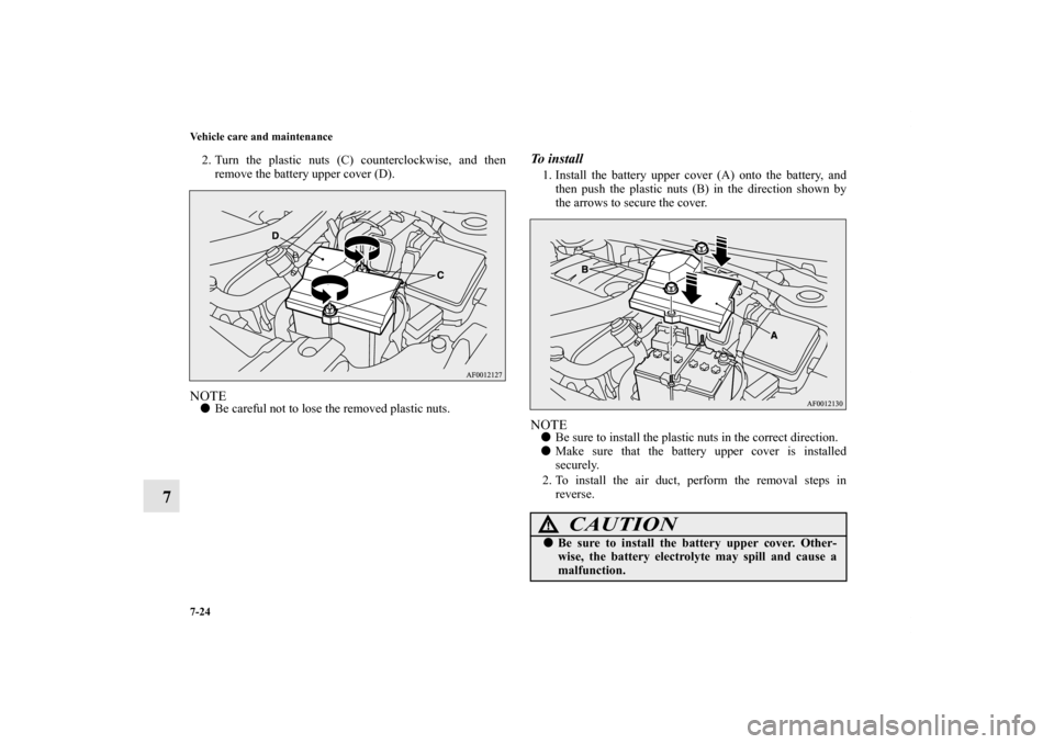
2. Turn the plastic nuts (C) counterclockwise, and then
remove the battery upper cover (D).NOTE�Be careful not to lose the removed plastic nuts.
To i n s t a l l1. Install the battery upper cover (A) onto the battery, and
then push the plastic nuts (B) in the direction shown by
the arrows to secure the cover. NOTE�Be sure to install the plastic nuts in the correct direction.
�Make sure that the battery upper cover is installed
securely.
2. To install the air duct, perform the removal steps in
reverse.
CAUTION
!�Be sure to install the battery upper cover. Other-
wise, the battery electrolyte may spill and cause a
malfunction.
BK0150800US.book 24 ページ 2012年3月29日 木曜日 午後2時38分
Page 624 of 722

Vehicle care and maintenance
7-25
7
Checking battery electrolyte level
N00901500014
The electrolyte level must be between the limits shown on the
outside of the battery. Fill it with distilled water as needed. The
inside of the battery is divided into several compartments. Take
the cap off of each compartment and fill to the mark.
Do not fill above the top line because a spill during driving
could cause damage.
NOTE�For vehicles equipped with a turbocharger, the battery
upper cover does not need to be removed to check the bat-
tery electrolyte level.During cold weather
N00901600015
The battery is weaker in cold temperatures. This has to do with
its chemical and physical properties and is why a very cold bat-
�When installing the battery upper cover, plastic
nuts, and air duct, do not touch the cooling fan or
other moving parts in the engine compartment. Be
especially careful that the cables, your clothing or
hair, etc., do not get caught in the cooling fan or
other moving parts.
CAUTION
!Except for vehicles with turbocharger
WA R N I N G
!�If the battery goes flat, be sure to check the battery
electrolyte level before connecting booster cables.�After checking the battery electrolyte level, make
sure the caps are fitted securely.�If any of the caps has a loose fit, replace the battery.Vehicles with turbocharger
BK0150800US.book 25 ページ 2012年3月29日 木曜日 午後2時38分

(if so equipped)
N00760300053
If an error code (1) appears in the display, take action in accordance with the table below.
Error display")
To r e m o v eTurn the pole (A) counterclockwise.To i n s t a l lScrew the pole (A) clockw")