Page 316 of 362

OutsideE01003302846
FrontType 1
1- Headlamps, high-beam: 60 W (HB3)
2- Headlamps, low beam: 55 W (H11)
3- Front turn-signal lamps: 21 W (PY21W)
4- Position lamps: 5 W (W5W)
5- Front fog lamps*: 55 W (H11)
6- Side turn-signal lamps (on fender)*: 5 W
(WY5W)
7- Side turn-signal lamps (on outside rear-view
mirror)*
Type 21- Headlamps, high/low beam: 60/55 W (H4)
2- Position lamps: 5 W (W5W)
3- Front turn-signal lamps: 21 W (PY21W)
4- Front fog lamps*: 55 W (H11)
5- Side turn-signal lamps (on fender)*: 5 W
(WY5W)
6- Side turn-signal lamps (on outside rear-view
mirror)*
Codes in parentheses indicate bulb types.
NOTE l The side turn-signal lamp (on outside rear-
view mirror) uses an LED instead of a bulb.
For repair and replacement, contact a
MITSUBISHI MOTORS Authorized Service
Point.
RearType 1Type 21- High-mounted stop lamp: 5 W (W5W)
2- Rear turn-signal lamps: 16 W (W16W)
3- Tail and stop lamps: 21/5 W (P21/5W)
4- Reversing lamps: 16 W (W16W)
5- Rear fog lamp (Type 1, Driver’s side only):
21 W (P21W)
6- Rear fog lamp (Type 2, Driver’s side only):
21 W (W21W)
7- Licence plate lamps: 5 W (W5W)
Codes in parentheses indicate bulb types.Inside E01003401518
Single cab
1- Door courtesy lamps*: 3.4 W
2- Room lamp: 8 W
3- Glove box lamp: 1.4 W
4- Centre console downlight: 1.4 W
Maintenance
8-24 OKTE13E1
8
Page 317 of 362

Club cab
1- Door courtesy lamps*: 3.4 W
2- Front room lamp and personal lamps*:
7.5 W
3- Rear room lamp: 8 W
4- Glove box lamp: 1.4 W
5- Centre console downlight: 1.4 W
Double cab
1- Door courtesy lamps*: 3.4 W
2- Front room lamp and personal lamps: 7.5 W
3- Rear room lamp*: 8 W
4- Glove box lamp: 1.4 W
5- Centre console downlight: 1.4 W
Headlamps E01003501375
Type 1 1.Remove the bulb and connector assembly
(A) by turning it anticlockwise.High beamLow beam2. Depress the tab (B) on the harness connector
and pull the harness connector (C) to remove
it.High beamLow beam
3. To install the bulb, perform the removal
steps in reverse.
CAUTIONl Handle halogen lamp bulbs with care.
The gas inside halogen lamp bulbs is high-
ly pressurized, so dropping, knocking, or
scratching a halogen lamp bulb can cause
it to shatter.
l Never hold the halogen lamp bulb with a
bare hand, dirty glove, etc.
The oil from your hand could cause the
bulb to break the next time the head-
lamps are operated.
If the glass surface is dirty, it must be
cleaned with alcohol, paint thinner, etc.,
and refit it after drying it thoroughly.
Maintenance
8-25
OKTE13E1
8
Page 318 of 362
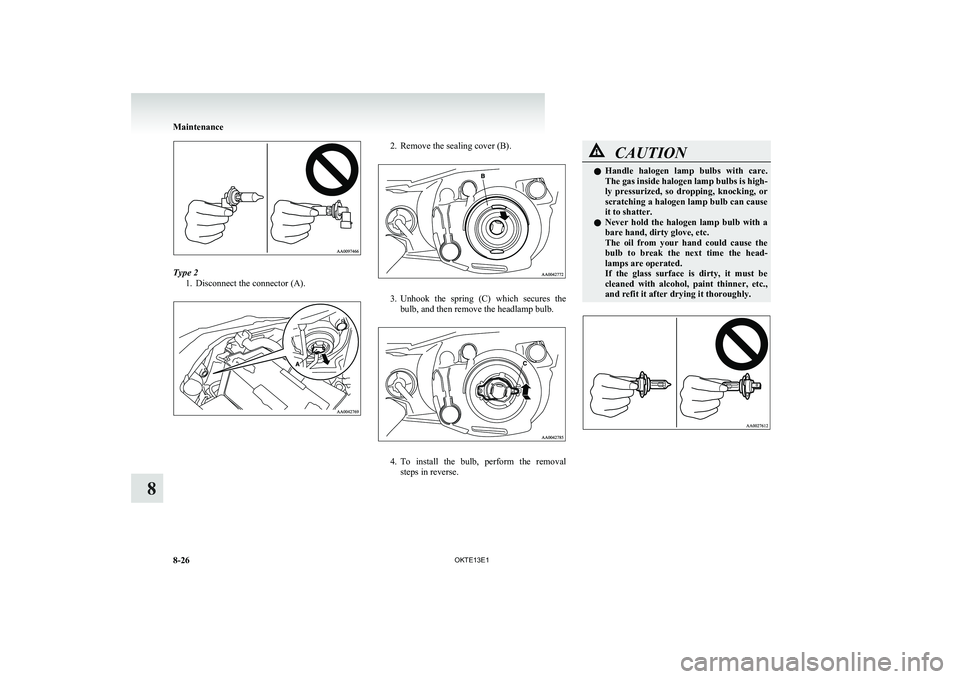
Type 21. Disconnect the connector (A).
2. Remove the sealing cover (B).
3.Unhook the spring (C) which secures the
bulb, and then remove the headlamp bulb.
4. To install the bulb, perform the removal
steps in reverse.
CAUTIONl Handle halogen lamp bulbs with care.
The gas inside halogen lamp bulbs is high-
ly pressurized, so dropping, knocking, or
scratching a halogen lamp bulb can cause
it to shatter.
l Never hold the halogen lamp bulb with a
bare hand, dirty glove, etc.
The oil from your hand could cause the
bulb to break the next time the head-
lamps are operated.
If the glass surface is dirty, it must be
cleaned with alcohol, paint thinner, etc.,
and refit it after drying it thoroughly.
Maintenance
8-26 OKTE13E1
8
Page 319 of 362
Position lampsE01003700833
Type 1 1.Turn the bulb socket anticlockwise to re-
move it. And remove the bulb from the sock-
et by pulling out.
2. To install the bulb, perform the removal
steps in reverse.
Type 2
1.Turn the bulb socket anticlockwise to re-
move it. And remove the bulb from the sock-
et by pulling out.
2. To install the bulb, perform the removal
steps in reverse.
Front turn-signal lamps E01003800818
Type 1
1.Turn the bulb socket anticlockwise to re-
move it. And remove the bulb from the sock-
et by turning it anticlockwise while pressing
in.
2. To install the bulb, perform the removal
steps in reverse.
Type 2 1.Turn the bulb socket anticlockwise to re-
move it. And remove the bulb from the sock-
et by turning it anticlockwise while pressing
in.
Maintenance
8-27
OKTE13E1
8
Page 320 of 362

2.To install the bulb, perform the removal
steps in reverse.Side turn-signal lamps (on fender)* E01003900633
1.To remove a side turn-signal lamp, insert a
straight blade (or minus) screwdriver at the
end of the lamp nearer the front of the body
and use it to gently lever the lamp out of the
body.
Front
NOTE
l Wrap a piece of cloth around the tip of the
screwdriver in order to avoid scratching the
lens and the body.
2. Remove the socket and bulb assembly togeth-
er by turning it anticlockwise, and then re-
move the bulb by pulling it out.
3. To install the bulb, perform the removal
steps in reverse.
NOTE l When replacing the lamp assembly, push in
the end facing the rear of the vehicle first.
FrontSide turn-signal lamps (on outside rear-
view mirrors)* E01003900646
The side turn-signal lamp (on outside rear-view mir-
ror) uses an LED instead of a bulb. For repair and
replacement, contact a MITSUBISHI MOTORS Au-
thorized Service Point.Front fog lamps* E01004001537
1.Insert a straight blade (or minus) screwdriver
with a cloth over its tip at the edge of the cov-
er and pry gently to remove the cover.
Type 1Type 2
Maintenance
8-28 OKTE13E1
8
Page 321 of 362
2.Turn the 3 bolts (A) anticlockwise to remove
them. And then remove the lamp assembly.
3. Depress the tab (B) on the harness connector
and pull the harness connector (C) to remove
it.
4. Turn the entire socket and bulb assembly (D)
anticlockwise to remove it.
5. To install the bulb, perform the removal
steps in reverse.
CAUTIONl Handle halogen lamp bulbs with care.
The gas inside halogen lamp bulbs is high-
ly pressurized, so dropping, knocking, or
scratching a halogen lamp bulb can cause
it to shatter.
l Never hold the halogen lamp bulb with a
bare hand, dirty glove, etc.
The oil from your hand could cause the
bulb to break the next time the fog lamps
are operated.
If the glass surface is dirty, it must be
cleaned with alcohol, paint thinner, etc.,
and refit it after drying thoroughly.Rear fog lamp E01004100384
Type 1 (Driver’s side only)
1.Remove the screws (A) from the rear fog
lamp lens, and then remove the lens (B).
Maintenance
8-29
OKTE13E1
8
Page 322 of 362

2.Remove the bulb (C) by turning it anticlock-
wise while pressing it inward.
3. To install the bulb, perform the removal
steps in reverse.
Type 2 (Driver’s side only) 1.Remove the socket and bulb assemblies by
turning it anticlockwise, and then remove the
bulb by pulling out.
2. To install the bulb, perform the removal
steps in reverse.
Rear combination lamps E01004200763
1. Open the rear gate.
(Refer to “Rear gate” on page 1-13.)
2. Remove the screws (A) that hold the lamp unit.
3.Move the lamp unit towards the rear of the ve-
hicle and remove the clips (B).
4. Remove each socket and bulb assembly by
turning it anticlockwise.C-Rear turn-signal lamp
Remove the bulb by pulling it out.D-Tail and stop lamp
Remove the bulb from the socket by turn-
ing it anticlockwise while pressing in.E-Reversing lamp
Remove the bulb by pulling it out.
5. To install the bulb, perform the removal
steps in reverse.
NOTE l When mounting the lamp unit, align the pins
(F) and clip (G) on the lamp unit with the
holes (H) in the body.
Maintenance
8-30 OKTE13E1
8
Page 323 of 362
High-mounted stop lampE01004500577
1. Open the rear gate.
(Refer to “Rear gate” on page 1-13.)
2. Remove the 8 screws (A) from the inner sur-
face of the rear gate. Remove the rear gate
cover (B).
3. Remove the socket and bulb assembly togeth-
er by turning it anticlockwise, and then re-
move the bulb by pulling it out.
4. To install the bulb, perform the removal
steps in reverse.
Licence plate lamps E01004601025
1.Insert a straight blade (or minus) screwdriver
into the lamp assembly and pry gently to re-
move it.
NOTE
l Wrap a piece of cloth around the tip of the
screwdriver in order to avoid scratching the
lens and the body.
2. Remove the socket and bulb assembly togeth-
er by turning it anticlockwise, and then re-
move the bulb by pulling it out.
3. To install the bulb, perform the removal
steps in reverse.
NOTE l When mounting the lamp unit, put the hook
(A) on the right side of the lamp unit into the
body first.
Maintenance
8-31
OKTE13E1
8