2013 MITSUBISHI L200 steering wheel
[x] Cancel search: steering wheelPage 81 of 362

WARNINGlDo not attach anything to the steering
wheel’s padded cover, such as trim mate-
rial, badges, etc. It might strike and in-
jure an occupant if the airbag inflates.
l Do not set anything on, or attach any-
thing to, the instrument panel above the
glove box. It might strike and injure an oc-
cupant if the airbag inflates.WARNINGl Do not attach accessories to, or put them
in front of, the windscreen. These objects
could restrict the airbag inflation, or
strike and injure an occupant if the air-
bags inflate.
l Do not put packages, pets or other ob-
jects between the airbags and the driver
or front passenger. It could affect airbag
performance, or could cause injury when
the airbag inflates.WARNINGl Right after the airbag inflation, several
airbag system components will be hot. Do
not touch them; you could be burned.
l The airbag system is designed to work on-
ly once. Once the airbags have deployed,
they will not work again. They must
promptly be replaced, and we recom-
mend you to have the entire airbag sys-
tem inspected by a MITSUBISHI
MOTORS Authorized Service Point.Side airbag system E00407600563
The side airbags (A) are contained in the driver and
front passenger seatbacks.
The side airbag is designed to inflate only on the
side of the vehicle that is impacted, even with no
passenger in the front seat.
The label shown here is attached to the seatbacks
with a side airbag.Curtain airbag system E00409100474
The curtain airbags are contained in the front pil-
lars and roof side rail. The curtain airbag is de-
signed to inflate only on the side of the vehicle that
is impacted, even with no passenger in the front
seat or rear seat.
Seat and seat belts
2-35
OKTE13E1
2
Page 85 of 362

SRS warning lampE00407801201
There is a Supplemental Restraint System (“SRS”)
warning lamp on the instrument panel. The system
checks itself and the lamp tells you if there is a prob-
lem. When the ignition switch is turned to the
“ON” or “START” position, the warning lamp
should illuminate for several seconds and then
should go out. This means the system is ready. If
an SRS airbag or pretensioner seat belt is not oper-
ating properly, the warning lamp comes on and
stays on.
The SRS warning lamp is shared by the SRS airbag
and the seat belt pretensioner system.WARNINGl If any of the following conditions occur,
the SRS and/or seat belt pretensioners
are not working properly, and we recom-
mend you to have it inspected by a
MITSUBISHI MOTORS Authorized
Service Point immediately.WARNING• The SRS warning lamp does not illu-
minate when you start the vehicle.
• The SRS warning lamp does not go
out after several seconds.
• The SRS warning lamp illuminates
while driving.SRS servicing E00407901244WARNINGlWe recommend any maintenance per-
formed on or near the components of the
SRS to be performed by a MITSUBISHI
MOTORS Authorized Service Point.
Improper work on the SRS components
or wiring could result in inadvertent de-
ployment of the airbags, or could render
the SRS inoperative; either situation
could result in serious injury.
l Do not modify your steering wheel, seat
belt retractor or any other SRS compo-
nents. For example, replacement of the
steering wheel, or modifications to the
front bumper or body structure can ad-
versely affect SRS performance and lead
to possible injury.
l If your vehicle has sustained any damage,
we recommend you to have the SRS in-
spected to ensure it is in proper working
order.WARNINGl On vehicles equipped with side airbags,
do not modify your front seats, centre pil-
lar and centre console.
It can adversely affect SRS performance
and lead to possible injury.
Also, if you have found any tear or open
seam in the seat fabric at the portion near
the side airbag, we recommend you to
have the seat inspected.
l On vehicles with the curtain airbags, if
you have found any scratch, crack or dam-
age to the portion of the front and rear pil-
lars and roof side rail, we recommend
you to have the SRS inspected by a
MITSUBISHI MOTORS Authorized
Service Point.
NOTE
l When you transfer ownership of the vehicle
to some other person, we urge you to alert
the new owner that it is equipped with the
SRS and refer the new owner to the applica-
ble section in this owner’s manual.
l If you junk or scrap the vehicle, we urge you
to first take the vehicle to a MITSUBISHI
MOTORS Authorized Service Point so that
the SRS can be rendered safe.
Seat and seat belts
2-39
OKTE13E1
2
Page 119 of 362

Switch position 0-Driver onlySwitch position 3-Driver + Full luggage load-
ing
{ Vehicles with heavy duty
suspension}Switch position 4-Driver + Full luggage load-
ing
{ Vehicles without heavy du-
ty suspension}
Double cab
Vehicle condi- tionSwitch position“0”“2” or “3” or“4”●:1 person:Full luggage loadingSwitch position 0-Driver onlySwitch position 2-Driver + Full luggage load-
ing
{ Vehicles with heavy duty
suspension for Russia, Ka-
zakhstan and Ukraine}Switch position 3-Driver + Full luggage load-
ing
{ Vehicles with heavy duty
suspension except for Rus-
sia, Kazakhstan and Uk-
raine}
{ Vehicles with headlamp -
type 2* and without heavy
duty suspension}Switch position 4-Driver + Full luggage load-
ing
{ Vehicles with headlamp -
type 1* and without heavy
duty suspension}
*: Refer to “Outside” on page 8-24
Turn-signals lever E00506501273
The turn-signal lamps flash when the lever is oper-
ated (with the ignition switch in the “ON” posi-
tion). At the same time, the turn-signal indication
lamps flash.
1- Turn-signals When making a normal turn, use position
(1). The lever will return automatically when
cornering is completed.
There are times when the lever will not re-
turn after cornering. This occurs when the
steering wheel is turned only slightly.
In such cases, return the lever by hand.
2- Lane-change signals When changing lanes, use position (2). It
will return to the neutral position when re-
leased.
NOTE l If the lamp flashes unusually quickly, the
bulb in a turn-signal lamp may have burned
out. We recommend you to have the vehicle
inspected.
Instruments and controls
3-33
OKTE13E1
3
Page 126 of 362

Rear window demister switchE00507900961
The rear window demister switch can be operated
with the ignition switch in the “ON” position.
Push the switch to turn on the rear window demis-
ter. It will be turned off automatically in about 20
minutes. To turn off the demister within about 20
minutes, push the switch again.
The indication lamp (A) will illuminate while the
demister is on.
Type 1Type 2NOTE
l If your vehicle is equipped with heated mir-
rors, these operate in conjunction with the de-
mister. Refer to “Heated mirror” on page
4-10.
l The demister switch is not to melt snow but
to clear mist. Remove snow before use of the
demister switch.
l To avoid unnecessary discharge of the bat-
tery, do not use the rear window demister dur-
ing starting of the engine or when the engine
is not running. Turn the demister off immedi-
ately after the window is clear.
l When cleaning the inside of the rear win-
dow, use a soft cloth and wipe gently along
the heater wires, being careful not to damage
the wires.
l Do not allow objects to touch the inside of
the rear window glass, or damaged or broken
wires may result.Horn switch E00508000608
Press the steering wheel on or around the “
” mark.
Type 1Type 2
Instruments and controls
3-40 OKTE13E1
3
Page 127 of 362

Economical driving.......................................................................4-02
Driving, alcohol and drugs ........................................................... 4-02
Safe driving techniques ................................................................ 4-03
Running-in recommendations.......................................................4-04
Parking brake ................................................................................ 4-06
Parking .......................................................................................... 4-07
Steering wheel height adjustment .................................................4-08
Inside rear-view mirror ................................................................. 4-08
Outside rear-view mirrors ............................................................. 4-09
Ignition switch .............................................................................. 4-10
Steering wheel lock ...................................................................... 4-12
Starting..........................................................................................4-12
Diesel particulate filter (DPF)* .................................................... 4-13
Manual transmission ..................................................................... 4-14
Automatic transmission Sports Mode 4A/T, 5A/T .......................4-17
Easy select 4WD* ......................................................................... 4-22
Super select 4WD* ....................................................................... 4-26
Rear differential lock* .................................................................. 4-31
4-wheel drive operation ................................................................ 4-35
Inspection and maintenance following rough road oper- ation .......................................................................................... 4-37
Cautions on handling of 4-wheel drive vehicles ..........................4-37
Limited-slip differential* .............................................................. 4-39
Braking ......................................................................................... 4-39
Brake assist system* ..................................................................... 4-40
Anti-lock brake system (ABS)* ................................................... 4-40
Power steering system .................................................................. 4-43
Active Stability & Traction Control (ASTC)* .............................4-43
Cruise control* ............................................................................. 4-46
Cargo loads ................................................................................... 4-50Trailer towing
............................................................................... 4-50Starting and driving
OKTE13E1
4
Page 134 of 362

Steering wheel height adjustmentE00600700219
To adjust the steering wheel height, release the tilt
lock lever while holding the steering wheel by
hand, and raise or lower the steering wheel to the
desired height.
After adjustment, securely lock the lever by pulling
it upward.
1- Locked
2- Release
WARNINGl After adjusting to the desired height,
check to be sure that the lever is locked.
l Do not attempt to adjust the steering
wheel while you are driving the vehicle.
l When releasing the tilt lock lever, move it
to the release position (2) and hold the
steering wheel by hand to prevent it fall-
ing to the lowest position.Inside rear-view mirror E00600800106
Adjust the rear-view mirror only after making any
seat adjustments so you have a clear view to the
rear of the vehicle.WARNINGl Do not attempt to adjust the rear-view
mirror while driving. This can be danger-
ous.
Always adjust the mirror before driving.
Adjust the rear-view mirror to maximize the view
through the rear window.
To adjust the vertical mirror position
It is possible to move the mirror up and down to ad-
just its position.
To reduce the glare
The lever (A) at the bottom of the mirror can be
used to adjust the mirror to reduce the glare from
the headlamps of vehicles behind you during night
driving.
1- Normal
2- Anti-glare
Starting and driving
4-08 OKTE13E1
4
Page 136 of 362

Push the switch to fold the mirrors inward, and
push the switch again to return them to extended po-
sition.
NOTE
l It is also possible to fold and return the mir-
rors by hand.
l When freezing has occurred and mirrors fail
to operate as intended, please refrain from re-
peated pushing of the retractor switch as this
action can result in burn-out of the mirror mo-
tor circuits.
Heated mirror* E00601200253
When the rear window demister switch (C) is press-
ed, the outside rear-view mirrors are demisted or de-
frosted. Current will flow through the heater ele-
ment inside the mirrors, thus clearing away frost or
condensation.
The indication lamp (D) will illuminate while the
demister is on. The heater will be turned off auto-
matically in about 20 minutes.Type 1Type 2
Ignition switch E00601402044
M/TA/T
LOCK
The engine is stopped and the steering wheel
locked. The key can only be inserted and removed
when the switch is in this position.
ACC
The engine is stopped, but the electrical devices
such as the radio and cigarette lighter can be operat-
ed.
ON
The engine is running, and all the vehicle’s electri-
cal devices can be operated.
START
The starter motor operates. After the engine has star-
ted, release the key and it will automatically return
to the “ON” position.
Starting and driving
4-10 OKTE13E1
4
Page 137 of 362
NOTEl If your vehicle is equipped with the Daytime
Running Lamp, when the ignition switch is
in the “ON”, the headlamp low beams etc.
are turned on.
Refer to “Headlamps” on page 3-30.
l Your vehicle is equipped with an electronic
immobilizer.
To start the engine, the ID code which the
transponder inside the key sends must match
the one registered in the immobilizer comput-
er.
Refer to “Electronic immobilizer” on page
1-03.
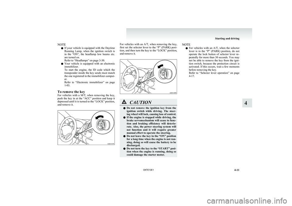
To remove the key
For vehicles with a M/T, when removing the key,
push the key in at the “ACC” position and keep it
depressed until it is turned to the “LOCK” position,
and remove it.For vehicles with an A/T, when removing the key,
first set the selector lever to the “P” (PARK) posi-
tion, and then turn the key to the “LOCK” position,
and remove it.CAUTIONl Do not remove the ignition key from the
ignition switch while driving. The steer-
ing wheel will lock, causing loss of control.
l If the engine is stopped while driving, the
brake servomechanism will cease to func-
tion and braking efficiency will deterio-
rate. Also, the power steering system will
not function and it will require greater
manual effort to operate the steering.
l Do not leave the key in the “ON” position
for a long time when the engine is not run-
ning, doing so will cause the battery to be
discharged.
l Do not turn the key to the “START” posi-
tion when the engine is running, doing so
could damage the starter motor.NOTE
l For vehicles with an
A/T, when the selector
lever is in the “P” (PARK) position, do not
operate the lock button of selector lever re-
peatedly for more than 30 seconds. You may
not be able to remove the key from the igni-
tion switch, because the protection circuit is
activated. If this occurs, wait a few moments
before removing the key.
Refer to “Selector lever operation” on page
4-17.
Starting and driving
4-11
OKTE13E1
4