2013 MITSUBISHI iMiEV steering wheel
[x] Cancel search: steering wheelPage 186 of 258

If the vehicle breaks down
E00800101355
If
the vehicle breaks down on the road, move it to
the shoulder and use the hazard warning flashers and/
or the warning triangle etc.
Refer to “Hazard warning flasher switch” on page
4-15. WARNING
l If
you are not able to safely assess the ve-
hicle due to vehicle damage, do not touch
the vehicle. Leave the vehicle and contact
a MITSUBISHI MOTORS Authorized
Service Point or another specialist and
convey that this is an electric vehicle first.
If the ready indicator goes out while
driving
Vehicle
operation and control are affected if the
ready indicator goes out while driving. Before mov-
ing the vehicle to a safe area, be aware of the fol-
lowing:
l The brake booster may become inoperative
and the pedal effort will increase. Press
down the brake pedal harder than usual.
l The power steering system may not operate,
the steering wheel feels heavy when turning it. Emergency starting
E00800502819
If
the electric motor unit cannot be started because
the auxiliary battery is weak or dead, the battery
from another vehicle can be used with jumper ca-
bles to start the electric motor unit. WARNING
l To
start the electric motor unit by using
jumper cables from another vehicle, per-
form the correct procedures according to
the instruction below. Incorrect proce-
dures could result in a fire or explosion
or damage to the vehicles. CAUTION
l
The
electric motor unit cannot be started
by pulling or pushing the vehicle.
l Always wear protective eye goggles when
working near the battery.
l Keep the battery out of the reach of chil-
dren.
l Do not attempt jump start the auxiliary
battery while the traction battery is being
charged.
Doing so could damage the charging
equipment or the vehicle.
1. Get
the vehicles close enough so the jumper cables can reach, but be sure the vehicles
aren’t touching each other. CAUTION
l
Check
the other vehicle. It must have a 12-
volt battery.
If the other system isn’t 12-volt, shorting
can damage both vehicles.
2. Turn
off all lamps, heater and other electrical loads.
3. Set the parking brake firmly on your vehicle and move the selector lever into the “P” posi-
tion.
4. Set the parking brake firmly on another vehi- cle. Put an A/T in “P” (PARK) or a M/T in
“N” (Neutral).
5. Turn the ignition switch or the electric motor switch to the “LOCK” position. WARNING
l Perform
step 5 on both vehicles before-
hand.
Make sure that the cables or your clothes
cannot be caught by the fan or drive belt.
Personal injury could result.
6. Remove
the battery cover, and then make sure auxiliary battery electrolyte is at the prop-
er level.
Refer to “Auxiliary battery” on page 8-12. For emergencies
7-02
7
OHAE13E1
Page 192 of 258

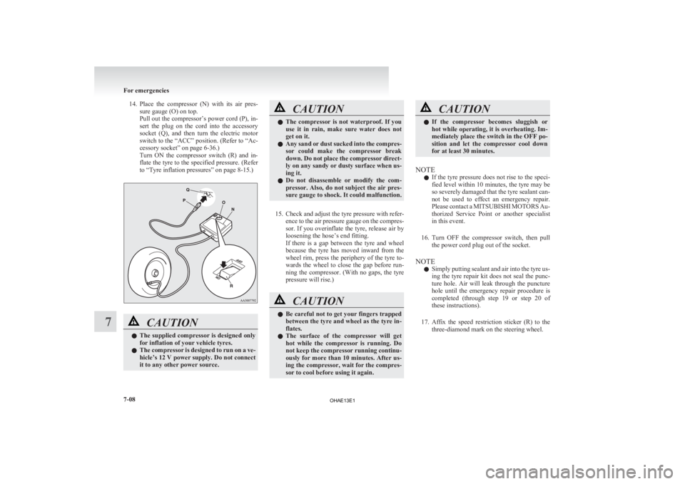
14. Place the compressor (N) with its air pres-
sure gauge (O) on top.
Pull out the compressor’s power cord (P), in-
sert the plug on the cord into the accessory
socket (Q), and then turn the electric motor
switch to the “ACC” position. (Refer to “Ac-
cessory socket” on page 6-36.)
Turn ON the compressor switch (R) and in-
flate the tyre to the specified pressure. (Refer
to “Tyre inflation pressures” on page 8-15.) CAUTION
l
The
supplied compressor is designed only
for inflation of your vehicle tyres.
l The compressor is designed to run on a ve-
hicle’s 12 V power supply. Do not connect
it to any other power source. CAUTION
l
The
compressor is not waterproof. If you
use it in rain, make sure water does not
get on it.
l Any sand or dust sucked into the compres-
sor could make the compressor break
down. Do not place the compressor direct-
ly on any sandy or dusty surface when us-
ing it.
l Do not disassemble or modify the com-
pressor. Also, do not subject the air pres-
sure gauge to shock. It could malfunction.
15. Check
and adjust the tyre pressure with refer- ence to the air pressure gauge on the compres-
sor. If you overinflate the tyre, release air by
loosening the hose’s end fitting.
If there is a gap between the tyre and wheel
because the tyre has moved inward from the
wheel rim, press the periphery of the tyre to-
wards the wheel to close the gap before run-
ning the compressor. (With no gaps, the tyre
pressure will rise.) CAUTION
l
Be
careful not to get your fingers trapped
between the tyre and wheel as the tyre in-
flates.
l The surface of the compressor will get
hot while the compressor is running. Do
not keep the compressor running continu-
ously for more than 10 minutes. After us-
ing the compressor, wait for the compres-
sor to cool before using it again. CAUTION
l
If
the compressor becomes sluggish or
hot while operating, it is overheating. Im-
mediately place the switch in the OFF po-
sition and let the compressor cool down
for at least 30 minutes.
NOTE l If
the tyre pressure does not rise to the speci-
fied level within 10 minutes, the tyre may be
so severely damaged that the tyre sealant can-
not be used to effect an emergency repair.
Please contact a MITSUBISHI MOTORS Au-
thorized Service Point or another specialist
in this event.
16. Turn OFF the compressor switch, then pull the power cord plug out of the socket.
NOTE l Simply putting sealant and air into the tyre us-
ing the tyre repair kit does not seal the punc-
ture hole. Air will leak through the puncture
hole until the emergency repair procedure is
completed (through step 19 or step 20 of
these instructions).
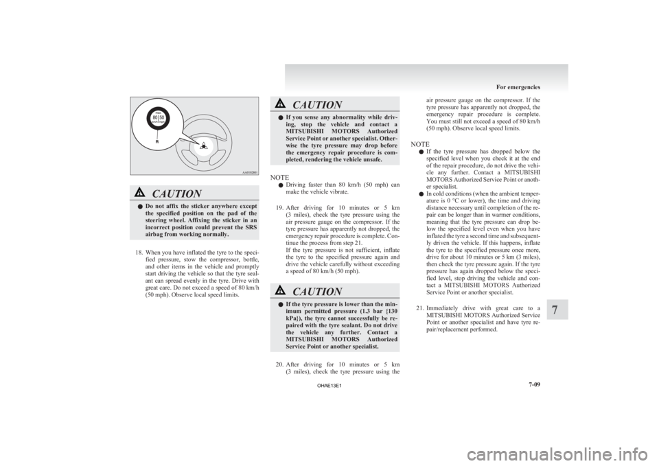
17. Affix the speed restriction sticker (R) to the three-diamond mark on the steering wheel. For emergencies
7-08
7
OHAE13E1
Page 193 of 258

CAUTION
l
Do not affix the sticker anywhere except
the specified position on the pad of the
steering wheel. Affixing the sticker in an
incorrect position could prevent the SRS
airbag from working normally.
18. When
you have inflated the tyre to the speci- fied pressure, stow the compressor, bottle,
and other items in the vehicle and promptly
start driving the vehicle so that the tyre seal-
ant can spread evenly in the tyre. Drive with
great care. Do not exceed a speed of 80 km/h
(50 mph). Observe local speed limits. CAUTION
l
If
you sense any abnormality while driv-
ing, stop the vehicle and contact a
MITSUBISHI MOTORS Authorized
Service Point or another specialist. Other-
wise the tyre pressure may drop before
the emergency repair procedure is com-
pleted, rendering the vehicle unsafe.
NOTE l Driving
faster than 80 km/h (50 mph) can
make the vehicle vibrate.
19. After driving for 10 minutes or 5 km (3 miles), check the tyre pressure using the
air pressure gauge on the compressor. If the
tyre pressure has apparently not dropped, the
emergency repair procedure is complete. Con-
tinue the process from step 21.
If the tyre pressure is not sufficient, inflate
the tyre to the specified pressure again and
drive the vehicle carefully without exceeding
a speed of 80 km/h (50 mph). CAUTION
l
If
the tyre pressure is lower than the min-
imum permitted pressure (1.3 bar {130
kPa}), the tyre cannot successfully be re-
paired with the tyre sealant. Do not drive
the vehicle any further. Contact a
MITSUBISHI MOTORS Authorized
Service Point or another specialist.
20. After
driving for 10 minutes or 5 km (3 miles), check the tyre pressure using the air pressure gauge on the compressor. If the
tyre
pressure has apparently not dropped, the
emergency repair procedure is complete.
You must still not exceed a speed of 80 km/h
(50 mph). Observe local speed limits.
NOTE l If the tyre pressure has dropped below the
specified level when you check it at the end
of the repair procedure, do not drive the vehi-
cle any further. Contact a MITSUBISHI
MOTORS Authorized Service Point or anoth-
er specialist.
l In cold conditions (when the ambient temper-
ature is 0 °C or lower), the time and driving
distance necessary until completion of the re-
pair can be longer than in warmer conditions,
meaning that the tyre pressure can drop be-
low the specified level even when you have
inflated the tyre a second time and subsequent-
ly driven the vehicle. If this happens, inflate
the tyre to the specified pressure once more,
drive for about 10 minutes or 5 km (3 miles),
then check the tyre pressure again. If the tyre
pressure has again dropped below the speci-
fied level, stop driving the vehicle and con-
tact a MITSUBISHI MOTORS Authorized
Service Point or another specialist.
21. Immediately drive with great care to a MITSUBISHI MOTORS Authorized Service
Point or another specialist and have tyre re-
pair/replacement performed. For emergencies
7-09 7
OHAE13E1
Page 195 of 258

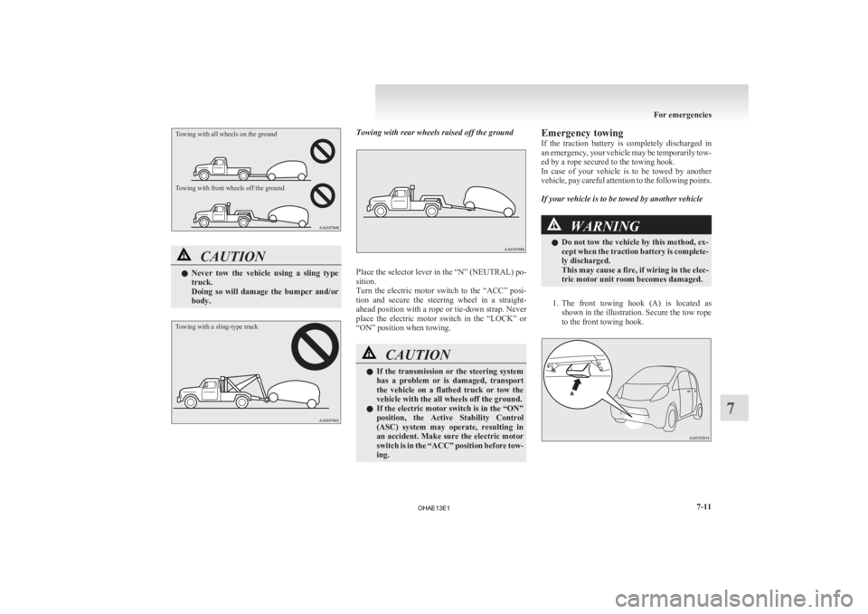
Towing with all wheels on the ground
Towing with front wheels off the groundCAUTION
l
Never
tow the vehicle using a sling type
truck.
Doing so will damage the bumper and/or
body.
Towing with a sling-type truck Towing with rear wheels raised off the ground
Place the selector lever in the “N” (NEUTRAL) po-
sition.
Turn
the electric motor switch to the “ACC” posi-
tion and secure the steering wheel in a straight-
ahead position with a rope or tie-down strap. Never
place the electric motor switch in the “LOCK” or
“ON” position when towing. CAUTION
l
If
the transmission or the steering system
has a problem or is damaged, transport
the vehicle on a flatbed truck or tow the
vehicle with the all wheels off the ground.
l If the electric motor switch is in the “ON”
position, the Active Stability Control
(ASC) system may operate, resulting in
an accident. Make sure the electric motor
switch is in the “ACC” position before tow-
ing. Emergency towing
If
the traction battery is completely discharged in
an emergency, your vehicle may be temporarily tow-
ed by a rope secured to the towing hook.
In case of your vehicle is to be towed by another
vehicle, pay careful attention to the following points.
If your vehicle is to be towed by another vehicle WARNING
l Do not tow the vehicle by this method, ex-
cept
when the traction battery is complete-
ly discharged.
This may cause a fire, if wiring in the elec-
tric motor unit room becomes damaged.
1. The
front towing hook (A) is located as shown in the illustration. Secure the tow rope
to the front towing hook. For emergencies
7-11 7
OHAE13E1
Page 196 of 258

NOTE
l Using
any part other than the designated tow-
ing hook (A) could result in damage to the ve-
hicle body.
l Using a wire rope or metal chain can result
in damage to the vehicle body. It is best to
use a non-metallic rope. If you use a wire
rope or metal chain, wrap it with cloth at any
point where it touches the vehicle body.
l Take care that the tow rope is kept as horizon-
tal as possible. An angled tow rope can dam-
age the vehicle body.
2. Start the electric motor unit. CAUTION
l
If
the vehicle is towed with the electric mo-
tor switch in the “ON” position without
starting the electric motor unit, the auxili-
ary battery may be flat during towing. In
this case, the brake performance may be
very poor. Steering is also very heavy.
l Do not leave the electric motor switch in
the “LOCK” position. The steering wheel
will lock, causing loss of control.
3. Place
the selector lever in the “N” (NEU- TRAL) position.
4. Turn on the hazard warning lamps if required by law. (Follow the local driving laws and
regulations.)
5. During towing make sure that close contact is maintained between the drivers of both ve-
hicles, and that the vehicles travel at low
speed. CAUTION
l
The
person in the vehicle being towed
must pay attention to the brake lamps of
the towing vehicle and make sure the
rope never becomes slack.
l Avoid sudden braking, sudden accelera-
tion and sharp turning; such operation
could cause damage to the towing hooks
or the tow rope.
People in the vicinity could be injured as
a result.
l When towing or being towed down a long
slope, the brakes may overheat reducing
the effectiveness. In this situation, have
your vehicle transported by a tow truck.
l When the vehicle is to be towed by anoth-
er vehicle with all wheels on the ground,
make sure that the towing speed and dis-
tance given below are never exceeded,
causing damage to the transmission.
Towing speed: 30 km/h (19 mph)
Towing distance: 30 km (19 miles)
For the towing speed and the towing dis-
tance, follow the local driving laws and
regulations.
Towing another vehicle
Your
vehicle cannot be used to tow another vehicle. Operation under adverse driving
conditions E00801702717
On a flooded road l Do
not drive on a flooded road. If you drive
on a flooded road, not only the electric motor
unit stops but also a failure like electric leak-
age or short circuit may occur.
If you inevitably had to run on a flooded
road and the vehicle was exposed to water,
be sure to have your vehicle inspected by a
MITSUBISHI MOTORS Authorized Service
Point.
l If there is water on the brakes after driving
through puddles or washing the vehicle, re-
sulting in temporarily ineffective brakes. In
such cases, lightly depress the brake pedal to
see if the brakes operate properly. If they do
not, lightly depress the pedal several times
while driving in order to dry the brake pads.
l When driving in rain or on a road with many
puddles a layer of water may form between
the tyres and the road surface.
This reduces a tyre’s frictional resistance on
the road, resulting in loss of steering stability
and braking capability.
To cope with this, observe the following items:
(a) Drive your vehicle at slow speed.
(b) Do not drive on worn tyres.
(c) Always maintain the specified tyre inflation pressures.For emergencies
7-12
7
OHAE13E1
Page 247 of 258

P
Parking 5-04
Parking brake 5-03
Position lamps Bulb capacity
8-24
Indication lamp 4-09
Replacement 8-30
Power down warning lamp 4-11
Precautions to observe when using wipers and wash-
ers 4-18
Pregnant women restraint 3-10
Puncture Tyre repair kit 7-04
QQuick charging 1-12
RRadio
LW/MW/FM electronic tuning radio with CD
player 6-10
Ready indicator
4-09
Rear combination lamps Bulb capacity 8-24
Replacement 8-33
Rear fog lamp Bulb capacity 8-24
Indication lamp 4-09
Replacement 8-32
Switch 4-16
Rear room lamp Bulb capacity 8-24
Rear seat 3-05
Rear turn-signal lamps Bulb capacity 8-24 Replacement 8-30,8-33
Rear window demister switch 4-18
Rear-view mirror Inside 5-05
Outside 5-05
Refill capacities
9-08
Regenerative braking 02
Regular charging 1-08
Replacement of lamp bulbs 8-23
Reversing lamps Bulb capacity 8-24
Replacement 8-33
Roof carrier precaution 5-20
Room lamp (front) 6-37
Room lamp (rear) 6-38
S Safe driving techniques 5-03
Seat belt 3-08
Child restraint 3-11
Force limiter
3-11
Inspection 3-20
Pregnant women restraint 3-10
Pretensioner 3-11
Seat belt reminder/warning lamp (for driver and
front passenger) 3-09
Warning lamp (for rear passenger) 3-10
Seats Adjustment 3-03
Front seat 3-03
Head restraints 3-07
Heated seats 3-04
Rear seat 3-05
Secret box 6-39
Selector lever 5-09
Service precaution 8-06
Service reminder 4-03,4-04
Side turn-signal lamps Bulb capacity 8-24
Replacement
8-30,8-33
Snow tyres 8-16
Specifications 9-02
Speedometer 4-02
Starting the electric motor unit 5-08
Steering wheel lock 5-08
Stop lamps Bulb capacity 8-24
Replacement 8-33
Storage spaces 6-39 Glove box 6-39
Secret box 6-39
Sun visors 6-35
Supplemental restraint system 3-20 Servicing 3-30
Warning lamp 3-29
T Tail lamps
Bulb capacity
8-24
Replacement 8-33
Tailgate 2-08
Towing 7-10
Traction battery 02
Transmission 5-09 Driving the vehicle 5-11
Selector lever 5-09
Selector lever position indicator 5-10
Tripmeter 4-03,4-04
Turn-signal indication lamps 4-09
Turn-signal lever 4-14
Tyre repair kit 7-04
Tyres 8-14 Inflation pressures 8-15
Size (tyre and wheel) 9-06
Snow tyres 8-16
Tread wear indicators 8-16 Alphabetical index
3
OHAE13E1