2013 MITSUBISHI iMiEV power steering
[x] Cancel search: power steeringPage 108 of 258

Indication and warning lamps
E00501502220Type 1Type 21-
Low energy warning indicator
® p. 4-07
2. Selector lever position indicator ® p. 5-10
3- High-beam indication lamp ® p. 4-09
4- Turn-signal indication lamps/Hazard warning indication lamps ® p. 4-09
5- Position lamp indication lamp ® p. 4-09
6- Front fog lamp indication lamp* ® p. 4-09
7- Service reminder ® p. 4-04
8- Driver’s and front passenger’s seat belt warning lamp ® p. 3-09
9- Supplement Restraint System (SRS) warning lamp ® p. 3-29
10- Rear fog lamp indication lamp ® p. 4-09
11- Ready indicator ® p. 4-09 12-
Auxiliary battery charge warning lamp ® p. 4-10
13- Electric power steering system (EPS) warning lamp ® p. 5-17
14- Electric motor unit warning lamp ® p. 4-10
15- Brake warning lamp ® p. 4-09
16- Anti-lock brake system (ABS) warning lamp ® p. 5-15
17- Power down warning lamp ® p. 4-11
18- Active stability control (ASC) indication lamp ® p. 5-19
19- Active stability control (ASC) OFF indication lamp ® p. 5-19
20- Charging indicator ® p. 4-09
21- Door ajar warning lamp ® p. 4-10
22- Rear passenger’s seat belt warning lamps* ® p. 3-10Instruments and controls
4-08 4
OHAE13E1
Page 121 of 258

Economical driving.......................................................................5-02
Driving, alcohol and drugs
........................................................... 5-02
Safe driving techniques ................................................................ 5-03
Parking brake................................................................................ 5-03
Parking.......................................................................................... 5-04
Inside rear-view mirror ................................................................. 5-05
Outside rear-view mirrors ............................................................. 5-05
Electric motor switch .................................................................... 5-07
Steering wheel lock ...................................................................... 5-08
Starting the electric motor unit ..................................................... 5-08
Transmission................................................................................. 5-09
Driving the vehicle ....................................................................... 5-11
Inspection
and maintenance following rough road oper-
ation.......................................................................................... 5-12
Acoustic Vehicle Alerting System (AVAS) .................................5-12
Braking......................................................................................... 5-14
Brake assist system....................................................................... 5-15
Anti-lock brake system (ABS) ..................................................... 5-15
Electric power steering system (EPS) ..........................................5-17
Active stability control (ASC) ...................................................... 5-18
Cargo loads................................................................................... 5-20
Trailer towing ............................................................................... 5-21Starting and driving
5
OHAE13E1
Page 125 of 258

Parking with the electric motor unit
running
Never
leave the electric motor unit running while
you take a short sleep/rest. WARNING
l Leaving
the electric motor unit running
risks injury or death from accidentally
moving the selector lever.
Do not keep the steering wheel fully
turned for a long time
More
effort could be required to turn the steering
wheel. Refer to “Electric power steering system
(EPS)” on page 5-17.
When leaving the vehicle
Always carry the key and lock all doors and the tail-
gate when leaving the vehicle unattended.
Always try to park your vehicle in a well lit area. Inside rear-view mirror
E00600800672
Adjust
the rear-view mirror only after making any
seat adjustments so you have a clear view to the
rear of the vehicle. WARNING
l Do
not attempt to adjust the rear-view
mirror while driving. This can be danger-
ous.
Always adjust the mirror before driving.
Adjust the rear-view mirror to maximize the view
through the rear window. Outside rear-view mirrors
E00600900628
To adjust the mirror position E00601000655
The outside rear-view mirrors can be operated
when
the electric motor switch is in the “ON” or
“ACC” position. WARNING
l Do
not attempt to adjust the rear-view
mirrors while driving. This can be danger-
ous.
Always adjust the mirrors before driving.
l Your vehicle is equipped with convex
type mirrors.
Please take into consideration, that ob-
jects you see in the mirror will look small-
er and farther away compared to a nor-
mal flat mirror.
Do not use this mirror to estimate dis-
tance of following vehicles when changing
lanes. Starting and driving
5-05 5
OHAE13E1
Page 127 of 258

Heated mirror*
E00601200514
To
demist or defrost the outside rear-view mirrors,
press the rear window demister switch.
The indication lamp (A) will illuminate while the
demister is on.
The heater will be turned off automatically in about
20 minutes. NOTE
l Since
the demister requires a significant
amount of power, stop the demister as soon
as the window is demisted. Electric motor switch
E00629400013 LOCK
The
steering wheel is locked. The key can only be
inserted and removed in this position.
ACC
The ready indicator is not illuminated, but the au-
dio system and other electric devices can be operat-
ed.
ON
The electric motor unit is running, and all the vehi-
cle’s electrical devices can be operated.
START
The electric motor unit operates. After the electric
motor unit has started, release the key and it will au-
tomatically return to the “ON” position. NOTE
l Your
vehicle is equipped with an electronic
immobilizer.
To start the electric motor unit, the ID code
which the transponder inside the key sends
must match the one registered in the immobil-
izer computer. Refer to “Electronic immobil-
izer (Anti-theft starting system)” on page
2-02.
To remove the key E00629500014
1. Set
the selector lever to the “P” (PARK) po-
sition.
2. Turn the key to the “LOCK” position and re- move it. Starting and driving
5-07 5
OHAE13E1
Page 128 of 258

CAUTION
l
If the ready indicator goes out while driv-
ing, the brake servomechanism will cease
to function and braking efficiency will de-
teriorate. Also, the power steering system
may not operate, the steering wheel feels
heavy when turning it.
l When the ready indicator has turned off,
turn the electric motor switch to the
“LOCK” position.
Leaving the electric motor switch in the
“ON” or “ACC” position and using elec-
trical devices such as the audio system for
a long time could cause the auxiliary bat-
tery to go flat and prevent the electric mo-
tor unit from being started. Steering wheel lock
E00601500692
To lock
Remove the key at the “LOCK” position.
Turn the steering wheel until it is locked.
To unlock
Turn
the key to the “ACC” position while moving
the steering wheel slightly right and left. CAUTION
l
Remove the key when leaving the vehicle.
In some countries, it is prohibited to leave
the key in the vehicle when parked. Starting the electric motor unit
E00629300012 CAUTION
l
Never
attempt to start the electric motor
unit by pushing or pulling the vehicle.
The starting procedure is as follows: 1. Insert
the key in the electric motor switch
and fasten the seat belt.
2. Make sure the parking brake is applied.
3. Depress and hold the brake pedal.
4. Make sure the selector lever is in the “P” (PARK) position. NOTE
l The
electric motor unit will not start unless
the selector lever is in the “P” (PARK) posi-
tion. Starting and driving
5-08
5
OHAE13E1
Page 137 of 258

After driving on icy roads
E00618800176
After
driving on snowy or icy roads, remove any
snow and ice which may have be left around the
wheels. Be careful not to damage the wheel speed
sensors (A) or the cables located at each wheel.
Front
Rear Electric power steering system
(EPS) E00629200183
The
power steering system operates while the elec-
tric motor unit is running. It helps reduce the effort
needed to turn the steering wheel.
The power steering system has mechanical steering
capability in case the power assist is lost. If the pow-
er assist is lost for some reason, you will still be
able to steer your vehicle, but you will notice it
takes much more effort to steer. If this happens,
have your vehicle inspected at a MITSUBISHI
MOTORS Authorized Service Point. WARNING
l Do
not stop the electric motor unit while
the vehicle is moving. Stopping the elec-
tric motor unit would make the steering
wheel extremely hard to turn, possibly re-
sulting in an accident.
NOTE l During
repeated full-lock turning of the steer-
ing wheel (for example, while you are ma-
noeuvring the vehicle into a parking space),
a protection function may be activated to pre-
vent overheating of the power steering sys-
tem. This function will make the steering
wheel gradually harder to turn. In this event,
limit your turning of the steering wheel for a
while. When the system has cooled down,
the steering action will return to normal. l
If
you turn the steering wheel while the vehi-
cle is stationary with the headlamps on, the
headlamps may become dim. This behaviour
is not abnormal. The headlamps will return
to their original brightness after a short while.
Electric power steering system warn-
ing lamp
Type 1
Type 2 If there is a malfunction in the system, the warning
lamp will come on. Starting and driving
5-17 5
OHAE13E1
Page 186 of 258

If the vehicle breaks down
E00800101355
If
the vehicle breaks down on the road, move it to
the shoulder and use the hazard warning flashers and/
or the warning triangle etc.
Refer to “Hazard warning flasher switch” on page
4-15. WARNING
l If
you are not able to safely assess the ve-
hicle due to vehicle damage, do not touch
the vehicle. Leave the vehicle and contact
a MITSUBISHI MOTORS Authorized
Service Point or another specialist and
convey that this is an electric vehicle first.
If the ready indicator goes out while
driving
Vehicle
operation and control are affected if the
ready indicator goes out while driving. Before mov-
ing the vehicle to a safe area, be aware of the fol-
lowing:
l The brake booster may become inoperative
and the pedal effort will increase. Press
down the brake pedal harder than usual.
l The power steering system may not operate,
the steering wheel feels heavy when turning it. Emergency starting
E00800502819
If
the electric motor unit cannot be started because
the auxiliary battery is weak or dead, the battery
from another vehicle can be used with jumper ca-
bles to start the electric motor unit. WARNING
l To
start the electric motor unit by using
jumper cables from another vehicle, per-
form the correct procedures according to
the instruction below. Incorrect proce-
dures could result in a fire or explosion
or damage to the vehicles. CAUTION
l
The
electric motor unit cannot be started
by pulling or pushing the vehicle.
l Always wear protective eye goggles when
working near the battery.
l Keep the battery out of the reach of chil-
dren.
l Do not attempt jump start the auxiliary
battery while the traction battery is being
charged.
Doing so could damage the charging
equipment or the vehicle.
1. Get
the vehicles close enough so the jumper cables can reach, but be sure the vehicles
aren’t touching each other. CAUTION
l
Check
the other vehicle. It must have a 12-
volt battery.
If the other system isn’t 12-volt, shorting
can damage both vehicles.
2. Turn
off all lamps, heater and other electrical loads.
3. Set the parking brake firmly on your vehicle and move the selector lever into the “P” posi-
tion.
4. Set the parking brake firmly on another vehi- cle. Put an A/T in “P” (PARK) or a M/T in
“N” (Neutral).
5. Turn the ignition switch or the electric motor switch to the “LOCK” position. WARNING
l Perform
step 5 on both vehicles before-
hand.
Make sure that the cables or your clothes
cannot be caught by the fan or drive belt.
Personal injury could result.
6. Remove
the battery cover, and then make sure auxiliary battery electrolyte is at the prop-
er level.
Refer to “Auxiliary battery” on page 8-12. For emergencies
7-02
7
OHAE13E1
Page 192 of 258

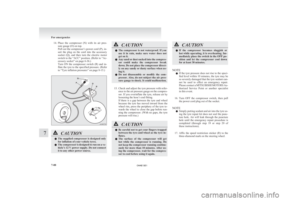
14. Place the compressor (N) with its air pres-
sure gauge (O) on top.
Pull out the compressor’s power cord (P), in-
sert the plug on the cord into the accessory
socket (Q), and then turn the electric motor
switch to the “ACC” position. (Refer to “Ac-
cessory socket” on page 6-36.)
Turn ON the compressor switch (R) and in-
flate the tyre to the specified pressure. (Refer
to “Tyre inflation pressures” on page 8-15.) CAUTION
l
The
supplied compressor is designed only
for inflation of your vehicle tyres.
l The compressor is designed to run on a ve-
hicle’s 12 V power supply. Do not connect
it to any other power source. CAUTION
l
The
compressor is not waterproof. If you
use it in rain, make sure water does not
get on it.
l Any sand or dust sucked into the compres-
sor could make the compressor break
down. Do not place the compressor direct-
ly on any sandy or dusty surface when us-
ing it.
l Do not disassemble or modify the com-
pressor. Also, do not subject the air pres-
sure gauge to shock. It could malfunction.
15. Check
and adjust the tyre pressure with refer- ence to the air pressure gauge on the compres-
sor. If you overinflate the tyre, release air by
loosening the hose’s end fitting.
If there is a gap between the tyre and wheel
because the tyre has moved inward from the
wheel rim, press the periphery of the tyre to-
wards the wheel to close the gap before run-
ning the compressor. (With no gaps, the tyre
pressure will rise.) CAUTION
l
Be
careful not to get your fingers trapped
between the tyre and wheel as the tyre in-
flates.
l The surface of the compressor will get
hot while the compressor is running. Do
not keep the compressor running continu-
ously for more than 10 minutes. After us-
ing the compressor, wait for the compres-
sor to cool before using it again. CAUTION
l
If
the compressor becomes sluggish or
hot while operating, it is overheating. Im-
mediately place the switch in the OFF po-
sition and let the compressor cool down
for at least 30 minutes.
NOTE l If
the tyre pressure does not rise to the speci-
fied level within 10 minutes, the tyre may be
so severely damaged that the tyre sealant can-
not be used to effect an emergency repair.
Please contact a MITSUBISHI MOTORS Au-
thorized Service Point or another specialist
in this event.
16. Turn OFF the compressor switch, then pull the power cord plug out of the socket.
NOTE l Simply putting sealant and air into the tyre us-
ing the tyre repair kit does not seal the punc-
ture hole. Air will leak through the puncture
hole until the emergency repair procedure is
completed (through step 19 or step 20 of
these instructions).
17. Affix the speed restriction sticker (R) to the three-diamond mark on the steering wheel. For emergencies
7-08
7
OHAE13E1