2013 MERCEDES-BENZ SLS AMG COUPE battery
[x] Cancel search: batteryPage 183 of 286

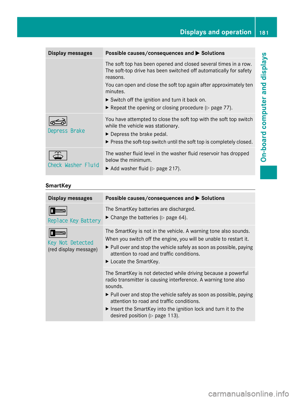
Display messages Possible causes/consequences and
0050
0050Solutions The soft top has been opened and closed several times in a row.
The soft-top drive has been switched off automatically for safety
reasons.
You can open and close the soft top again after approximately ten
minutes.
X
Switch off the ignition and turn it back on.
X Repeat the opening or closing procedure (Y page 77).0059
Depress Brake Depress Brake You have attempted to close the soft top with the soft top switch
while the vehicle was stationary.
X
Depress the brake pedal.
X Press the soft-top switch until the soft top is completely closed. 00B2
Check Washer Fluid Check Washer Fluid The washer fluid level in the washer fluid reservoir has dropped
below the minimum.
X
Add washer fluid ( Ypage 217). SmartKey
Display messages Possible causes/consequences and
0050 0050Solutions 0039
Replace Replace
Key
KeyBattery
Battery The SmartKey batteries are discharged.
X
Change the batteries ( Ypage 64). 0039
Key Not Detected Key Not Detected
(red display message) The SmartKey is not in the vehicle. A warning tone also sounds.
When you switch off the engine, you will be unable to restart it.
X
Pull over and stop the vehicle safely as soon as possible, paying
attention to road and traffic conditions.
X Locate the SmartKey. The SmartKey is not detected while driving because a powerful
radio transmitter is causing interference. A warning tone also
sounds.
X
Pull over and stop the vehicle safely as soon as possible, paying
attention to road and traffic conditions.
X Insert the SmartKey into the ignition lock and turn it to the
desired position ( Ypage 113). Displays and operation
181On-board computer and displays Z
Page 202 of 286

Example: Coupe
X
Select key position 2with the Start/Stop
button.
X To open: briefly press the middle of
cover 0043.
The stowage compartment opens.
X Press in cigarette lighter 0044.
Cigarette lighter 0044will pop out
automatically when the heating element is
red-hot.
X To close: fold down cover 0043. 12 V sockets
Points to observe before use X
Turn the SmartKey to position 1in the
ignition lock (Y page 113).
The sockets can be used for accessories with
a maximum current draw of 180 W (15 A), e.g.
lamps or chargers for mobile phones.
If you use the sockets for long periods when
the engine is switched off, the battery may
discharge.
i You can also use the sockets when the
ignition is switched off. An emergency cut-
out ensures that the on-board voltage does
not drop too low. If the on-board voltage is
too low, the power to the sockets is
automatically cut. This ensures that there
is sufficient power to start the engine. Socket in the glove box
X
Open the glove box (Y page 196).
Lift up the cover of socket 0043.
Socket on the center console !
If accessories are connected, make sure
that a maximum current draw of 15 A is not
exceeded. Otherwise, you will overload the
fuse. Example: Coupe
X
To open: briefly press the middle of
cover 0043.
The stowage compartment opens.
X Lift up the cover of socket 0044.
X To close: fold down cover 0043.200
FeaturesSto
wage an d features
Page 203 of 286

mbrace
7
Important safety notes !
You must have a license agreement to
activate the mbrace service. Ensure that
your system is activated and ready for use,
and press the 00D9MB Info call button to
register. If one of these steps is not carried
out, it may not be possible to activate the
system.
If you have questions about the activation,
contact one of the following telephone
hotlines:
R USA: Mercedes-Benz Customer
Assistance center at
1-800-FOR-MERCedes
(1-800-367-6372) or 1-866-990-9007
R Canada: Customer Service at
1-888-923-8367
Shortly after successfully registering with the
mbrace service, a user ID and password will
be sent to you by mail. You can use this
password to log onto the mbrace area under
"Owners Online" at http://
www.mbusa.com 8
.
The mbrace system is available if:
R it has been activated and is operational
R the corresponding mobile phone network
is available for transmitting data to the
Customer Center
R a service subscription is available
R the starter battery is sufficiently charged
i Determining the location of the vehicle on
a map is only possible if there is sufficient
GPS reception and the vehicle position can
be forwarded to the Customer Center. The mbrace system The mbrace system provides various
services, e.g.:
R
automatic and manual emergency call
R Roadside Assistance call
R MB Info call
To adjust the volume during an mbrace call,
proceed as follows:
X Press the 0081or0082 button on the
multifunction steering wheel.
or
X Use the volume controller of COMAND.
You can find further information and a
description of all available features under
"Owners Online" at http://
www.mbusa.com 9
.
Self-diagnosis of the system After you have switched on the ignition, the
system carries out a self-diagnosis.
A malfunction in the system has been
detected if one of the following conditions
occurs:
R
the indicator lamp in the SOS button does
not light up during the system self-
diagnosis.
R the indicator lamp in the 0052Roadside
Assistance button does not light up during
the system self-diagnosis.
R the indicator lamp in the 00D9information
button does not light up during self-
diagnosis of the system.
R the indicator lamp in the SOS button, the
0052 Roadside Assistance button or the
00D9 information button continues to light
up red after the system self-diagnosis.
R the Tele
Tele Aid AidInoperative
Inoperative orTele
Tele Aid
Aid
Not Activated
Not Activated message appears in the
multifunction display after the system self-
diagnosis.
7 The system is called TELE AID in Canada.
8 USA only.
9 USA only. Features
201Stowage an d features Z
Page 213 of 286

same programming steps with this remote
control. Before performing these steps,
make sure that new batteries have been
installed in garage door drive remote
control
0083.
R Note that some remote controls only
transmit for a limited amount of time (the
indicator lamp on the remote control goes
out). Press button 0084on remote control
0083 again before transmission ends.
R Align the antenna cable of the garage door
opener unit. This can improve signal
reception/transmission.
Opening/closing the garage door Once programmed, the integrated garage
door opener 0083will assume the function of
the garage door system's remote control.
Please also read the operating instructions
for the garage door system.
X Select key position 2with the Start/Stop
button.
X Press button 0044,0087or0085 which you have
programmed to operate the garage door.
Garage door system with a fixed code:
indicator lamp 0043lights up green.
Garage door system with a rolling code:
indicator lamp 0043flashes green.
i The transmitter will transmit a signal as
long as the button is pressed. The
transmission is halted after a maximum of
ten seconds and indicator lamp 0043lights
up yellow. Press button 0044,0087or0085 again
if necessary.
Clearing the memory of the integrated
garage door opener on the rear-view
mirror X
Select key position 2with the Start/Stop
button.
X Press buttons 0044and 0085.
The indicator lamp lights up yellow.
X Press and hold buttons 0044and 0085until the
indicator lamp turns green. i
Make sure that you clear the memory of
the integrated garage door opener before
selling the vehicle. Charge maintenance socket
The battery may drain if the vehicle is left
stationary for long periods. In this case,
Mercedes-Benz recommends attaching the
trickle charger to the charge maintenance
socket.
The charge maintenance socket is designed
solely for connecting a trickle charger. A
trickle charger can be obtained from an
authorized Mercedes-Benz Center, for
example. X
Switch the ignition off.
X Open the trunk lid.
X Connect the cable provided in the trunk to
the trickle charger.
X Connect the trickle charger to charge
maintenance socket 0043. Consult the
manufacturer's operating instructions on
how to do so.
i A trickle charger connected to charge
maintenance socket 0043only maintains the
current charge level of the vehicle's
electrical system battery. If the vehicle's
electrical system battery is discharged, it
needs to be charged with a battery charger.
You will find further information on
charging the battery on (Y page 236). Features
211Stowage and features Z
Page 220 of 286

You can obtain further information from an
authorized Mercedes-Benz Center or at
http://www.mbusa.com (USA only).
The service interval message informs you of
the next service due date.
If a service due date has been exceeded, you
also hear a warning tone.
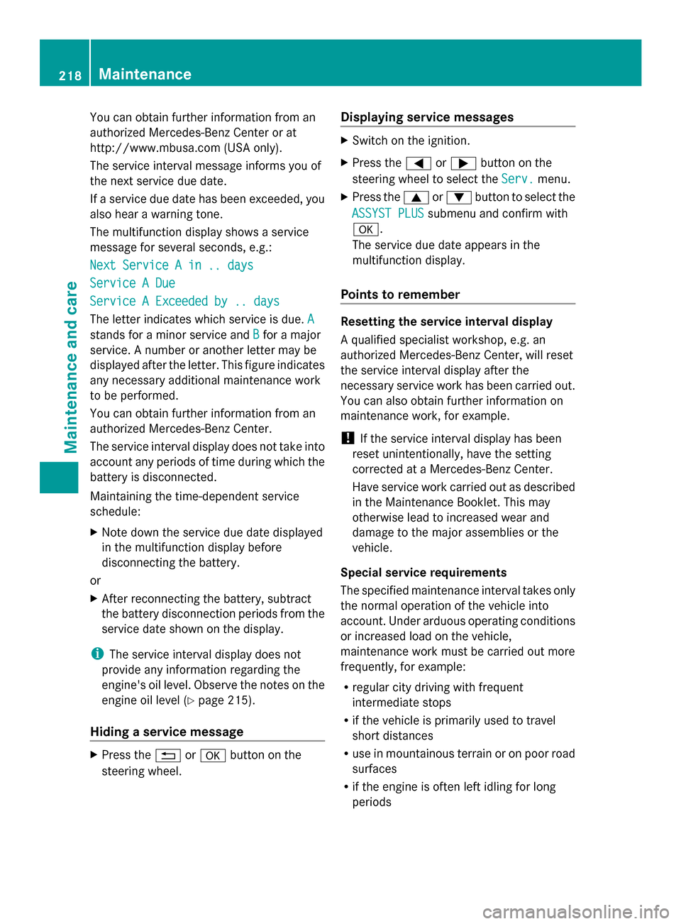
The multifunction display shows a service
message for several seconds, e.g.:
Next Service A in .. days
Next Service A in .. days
Service A Due Service A Due
Service A Exceeded by .. days Service A Exceeded by .. days
The letter indicates which service is due. A A
stands for a minor service and B
Bfor a major
service. A number or another letter may be
displayed after the letter. This figure indicates
any necessary additional maintenance work
to be performed.
You can obtain further information from an
authorized Mercedes-Benz Center.
The service interval display does not take into
account any periods of time during which the
battery is disconnected.
Maintaining the time-dependent service
schedule:
X Note down the service due date displayed
in the multifunction display before
disconnecting the battery.
or
X After reconnecting the battery, subtract
the battery disconnection periods from the
service date shown on the display.
i The service interval display does not
provide any information regarding the
engine's oil level. Observe the notes on the
engine oil level (Y page 215).
Hiding a service message X
Press the 0041or0076 button on the
steering wheel. Displaying service messages X
Switch on the ignition.
X Press the 0059or0065 button on the
steering wheel to select the Serv. Serv.menu.
X Press the 0063or0064 button to select the
ASSYST PLUS
ASSYST PLUS submenu and confirm with
0076.
The service due date appears in the
multifunction display.
Points to remember Resetting the service interval display
A qualified specialist workshop, e.g. an
authorized Mercedes-Benz Center, will reset
the service interval display after the
necessary service work has been carried out.
You can also obtain further information on
maintenance work, for example.
!
If the service interval display has been
reset unintentionally, have the setting
corrected at a Mercedes-Benz Center.
Have service work carried out as described
in the Maintenance Booklet. This may
otherwise lead to increased wear and
damage to the major assemblies or the
vehicle.
Special service requirements
The specified maintenance interval takes only
the normal operation of the vehicle into
account. Under arduous operating conditions
or increased load on the vehicle,
maintenance work must be carried out more
frequently, for example:
R regular city driving with frequent
intermediate stops
R if the vehicle is primarily used to travel
short distances
R use in mountainous terrain or on poor road
surfaces
R if the engine is often left idling for long
periods 218
MaintenanceMaintenance and care
Page 223 of 286

X
Use plenty of water and rinse out the
sponge frequently.
X Rinse the vehicle with clean water and dry
thoroughly with a chamois.
X Do not let the cleaning agent dry on the
paintwork.
Carefully remove all deposits of road salt as
soon as possible when driving in winter.
Power washers G
WARNING
The water jet from a circular jet nozzle (dirt
blasters) can cause invisible exterior damage
to the tires or chassis components.
Components damaged in this way may fail
unexpectedly. There is a risk of an accident.
Do not use power washers with circular jet
nozzles to clean the vehicle. Have damaged
tires or chassis components replaced
immediately.
! Maintain a minimum distance of
11.8 in (30 cm) between the vehicle and the
power washer nozzle. Information about
the correct distance is available from the
equipment manufacturer.
Move the power washer nozzle around
when cleaning your vehicle.
Do not aim directly at any of the following:
R tires
R door gaps, roof gaps, joints, etc.
R electrical components
R battery
R connectors
R lights
R seals
R trim elements
R ventilation slots
Damaged seals or electrical components
can lead to leaks or failures. Cleaning the wheels !
Do not use acidic wheel cleaning products
to remove brake dust. This could damage
wheel bolts and brake components.
! Do not park the vehicle for an extended
period right after cleaning it, particularly
after having cleaned the wheels with wheel
cleaner. Wheel cleaners could cause
increased corrosion of the brake discs and
brake pads/linings. For this reason, you
should drive for a few minutes after
cleaning. Braking heats the brake discs and
brake pads, thus drying them. The vehicle
can then be parked.
Cleaning the paintwork Scratches, corrosive deposits, areas affected
by corrosion and damage caused by
inadequate care cannot always be completely
repaired. In such cases, visit a qualified
specialist workshop, e.g. an authorized
Mercedes-Benz Center.
X
Remove impurities immediately, where
possible, whilst avoiding rubbing too hard.
X Soak insect remains with insect remover
and rinse off the treated areas afterwards.
X Soak bird droppings with water and rinse
off the treated areas afterwards.
X Remove coolant, brake fluid, tree resin,
oils, fuels and greases by rubbing gently
with a cloth soaked in petroleum ether or
lighter fluid.
X Use tar remover to remove tar stains.
X Use silicone remover to remove wax.
! Do not affix:
R stickers
R films
R magnetic plates or similar items
to painted surfaces. You could otherwise
damage the paintwork.
If water no longer forms "beads" on the paint
surface, use the paint care products
recommended and approved by Mercedes- Care
221Maintenance and care Z
Page 229 of 286

Useful information
............................228
Where will I find...? ...........................228
Flat tire .............................................. 229
Battery ............................................... 236
Jump-starting .................................... 240
Towing and tow-starting ..................242
Fuses .................................................. 244 227Breakdown assistance
Page 232 of 286

X
Do not remove any foreign objects which
have penetrated the tire, e.g. screws or
nails.
X Take the TIREFIT kit out of the trunk
(Y page 228). X
Open the TIREFIT kit and remove "max.
80 km/h" sticker 006C.
X Affix sticker 006Cwithin the driver's field of
vision.
i If TIREFIT leaks out, allow it to dry. It can
then be removed like a layer of film.
If you get TIREFIT on your clothing, have it
cleaned as soon as possible with
perchloroethylene.
Comply with the manufacturer's safety
instructions on the tire inflation compressor
label and on the tire sealant bottle.
i You will also find operating instructions
0087 in the lid of the TIREFIT kit.
X Pull the cable and filler hose 006Dout of the
housing. X
Unscrew flanged cap 0083. X
Unscrew the cap from tire sealant
bottle 0043. Make sure that the aluminum
film is not damaged when doing so. X
Screw tire sealant bottle 0043clockwise
tightly onto flange seal 006E.
This pierces the aluminum film.
X Remove the cap from the valve on the faulty
tire.
X Make sure that pressure release screw 006B
is closed.
X Remove the dust protection cap from filler
hose 006D. X
Screw the end of filler hose 006Donto tire
valve 006F.
X Make sure that on/off switch 0044on the tire
inflation compressor is set to 0.
X Insert connector 0085into the 12 V cigarette
lighter socket ( Ypage 199).
X Select key position 2with the Start/Stop
button ( Ypage 113).
i The battery discharges during tire
inflation compressor usage. For this 230
Flat tireBreakdown assistance