2013 MERCEDES-BENZ M-Class weight
[x] Cancel search: weightPage 343 of 458

Inserting the brackets int
othe loading
rail X
Insert bracket 0002into the center of loading
rail 001E.
X Press release button 0003and push
bracket 0002into the desired position in
loading rail 001E.
X Let go of release button 0003.
X Press locking button 001F.
Bracket 0002is locked in loading rail 001E.
X If necessary, fold cargo tie-dow nring 001C
upwards.
Luggage holder !
Only use the luggage holder to secure
cargo with a maximum weight of 15.4 lbs
(7 kg) and with dimensions that the luggage
holder can safely and securely contain. The luggage holder can be used to secure
light loads against the side wall of the cargo
compartment to prevent them from moving
around. X
To install: insert two brackets 001Cinto the
left or right loading rail (Y page 340).
X Press release button 0002of the luggage
holder and pull the strap out slightly.
X Insert luggage holder 0003into brackets 001C
and, while doing so, press release button
001F and push the luggage holder downwards
until it engages.
X Press release button 0002of the luggage
holder and pull the strap out in the direction
of the arrow.
X Place the load between the strap and the
cargo compartmen tside wall.
X Using one hand, press locking button 0002of
the luggage holder.
X With your other hand, let the strap go slowly
until the load is secured.
X Make sure that locking button 001Eon
brackets 001Cis pressed.
This keeps brackets 001Cin place on the
loading rail.
X To remove: press release button 001Fon
respective bracket 001Cand remove luggage
holder 0003by pulling upwards and out.
Telescopic rod The telescopic rod can be used to secure the
load against the rear seats to prevent it from
moving around. Stowage areas
341Stowage and features Z
Page 346 of 458

The bottles are not secured or prevented from
tipping over. Therefore, do not place any open
drink containers in the stowage
compartments.
Cup holder in the front-compartment
center console
0002
Cup holder
0003 Cover
X To open: slide cover 0003to its foremost
position.
X To close: pull cover 0003back as far as it will
go.
You can remove the cup holder's rubber mat
for cleaning. Clean with clear, lukewarm
water only.
Temperature-controlled cup holder in
the front-compartment center console 0002
Cup holder
0003 Residual heat indicator lamp
001F Switch The temperature-controlled cup holder can
be used to keep cold drink
scool and warm
drinks warm.
X Turn the SmartKey to position 2in the
ignition lock.
X To switch on the cooling function: press
and hold button 001Funtil the blue indicator
lamp on the button lights up.
X To switch on the heating function: press
and hold button 001Funtil the red indicator
lamp on the button lights up.
X To switch off the function: press and hold
button 001Funtil the indicator lamp on the
button goes out.
When the heating function is used, the metal
insert of the cup holder is heated. Once a
certain temperature is reached, residual heat
indicator lamp 0003lights up. This means that
the metal insert of the cup holder is hot. For
this reason, you must not reach into the cup
holder metal insert.
Do not use hard or sharp objects to clean the
cup holder. Use only a soft cloth to clean it.
Cup holder in the rear seat armrest !
Do not sit on or support your body weight
on the rear seat armrest when it is folded
down, as you could otherwise damage it. X
Fold down the rear seat armrest.
Cup holder 0002is located in the rear seat
armrest. 344
FeaturesStowage and features
Page 393 of 458

X
Slide cover 0002of positive terminal 0003in the direction of the arrow.
X Connect positive terminal 0003on your vehicle to positive terminal 001Fof donor battery 001D
using the jumper cable, always begi nwith positive terminal 0003on your own vehicle first.
X Start the engine of the dono rvehicle and run it at idling speed.
X Connec tnegative terminal 001Eof donor battery 001Dto ground point 001Cof your vehicle using
the jumper cable, connecting the jumper cable to donor battery 001Dfirst.
X Start the engine.
X Before disconnecting the jumper cables, let the engin erun for several minutes.
X First, remove the jumper cables from earth point 001Cand negative terminal 001E, then from
positive clamp 0003and positive terminal 001F. Begin each time at the contacts on your own
vehicle first.
X Close cover 0002of positive terminal 0003after removing the jumper cables.
X Have the battery checke dataqualified specialist workshop.
i Jump-starting is not considered to be a normal operating condition.
i Jumper cables and further information regarding jump-starting can be obtained at any
qualified specialist workshop. Towing and tow-starting
Important safety notes
G
WARNING
Functions relevant to safety are restricted or
no longer available if:
R the engine is not running.
R the brake system or the power steering is
malfunctioning.
R there is a malfunction in the voltage supply
or the vehicle's electrical system.
If your vehicle is being towed, much more
force may be necessary to steer or brake.
There is a risk of an accident.
In such cases, use a tow bar. Before towing,
make sure that the steering moves freely. G
WARNING
If the weight of the vehicle to be towed or tow-
started is greater than the permissible gross
weight of your vehicle:
R the towing eye could detach itself
R the vehicle/trailer combination could
rollover. There is a risk of an accident.
When towing or tow-starting another vehicle,
its weight should not be greater than the
permissible gross weight of your vehicle.
G
WARNING
The vehicle is braked when the HOLD function
or DISTRONIC PLUS is activated. Therefore,
deactivate HOLD and DISTRONIC PLUS if the
vehicle is to be towed.
! Make sure that the electric parking brake
is released. If the electric parking brake is
faulty, visit a qualified specialist workshop.
! Only secure the tow rope or tow bar at the
towing eyes. Otherwise, the vehicle could
be damaged.
! Do not use the towing eye for recovery,
this could damage the vehicle. If in doubt,
recover the vehicle with acrane.
! When towing, pull away slowly and
smoothly .Ifthe tractive power is too high,
the vehicles could be damaged. Towing and tow-starting
391Breakdown assistance Z
Page 394 of 458

!
When towing vehicles with KEYLESS-GO,
use the key instead of the Start/Stop
button. Otherwise, the automatic
transmission may shift to position Pwhen
the driver's or front-passenger door are
opened, which could lead to damage to the
transmission.
! Do not tow with sling-type equipment.
This could damage the vehicle.
! Vehicles with differential locks: make
sure the differential locks are in automatic
mode. When towing, the differential locks
must not be switched on. The transmission
may otherwise be damaged.
! The vehicle can be towed a maximum of
30 miles (50km). The towing speed of
30 mph (50 km/h) must not be exceeded.
If the vehicle has to be towed more than
30 miles (50km), the entire vehicle must be
raised and transported.
! If you tow or tow-start another vehicle, its
weight must not exceed the maximum
permissible gross vehicle weight of your
vehicle.
Information on your vehicle's gross vehicle
weight rating can be found on the vehicle
identification plate (Y page 443).
It is better to have the vehicle transported
than to have it towed.
If the vehicle has suffered transmission
damage, have it transported on a transporter
or trailer.
The automatic transmission must be in
position Nwhen the vehicle is being towed.
The battery must be connected and charged.
Otherwise, you:
R cannot turn the SmartKey to position 2in
the ignition lock
R cannot release the electric parking brake
R cannot shift the automatic transmission to
position N
i Deactivate the automatic locking feature
(Y page 276). You could otherwise be locked out when pushing or towing the
vehicle. Installing/removing the towing eye
Installing the towing eye Example: towing eye mounting covers
0002 Front cover
0003 Back cover
Vehicles with a trailer tow hitch: if possible,
connect the towbar to the trailer tow hitch
(Y page 253).
The brackets for the screw-in towing eyes are
located in the bumpers. They are at the front
and at the rear, under the covers.
X Remove the towing eye from the vehicle
tool kit (Y page 380).
X To open the cover at the front: press the
mark on cover 0002inwards in the direction
of the arrow.
X To open the cover at the rear: insert a
flat, blunt object into the cutout and lever
cover 0003out of the bumper.
X Take cover 0002or0003 off the opening.
X Screw the towing eye in clockwise to the
stop and tighten it. 392
Towing and tow-startingBreakdown assistance
Page 412 of 458

Loading the vehicle
Instruction labels for tires and loads
G
WARNING
Overloaded tires can overheat, causing a
blowout .Overloaded tires can also impair the
steering and driving characteristics and lead
to brake failure. There is a risk of accident.
Observe the load rating of the tires. The load
rating must be at least halfoft he GAWR of
your vehicle. Never overload the tires by
exceeding the maximum load.
Two instruction labels on your vehicle show
the maximum possible load.
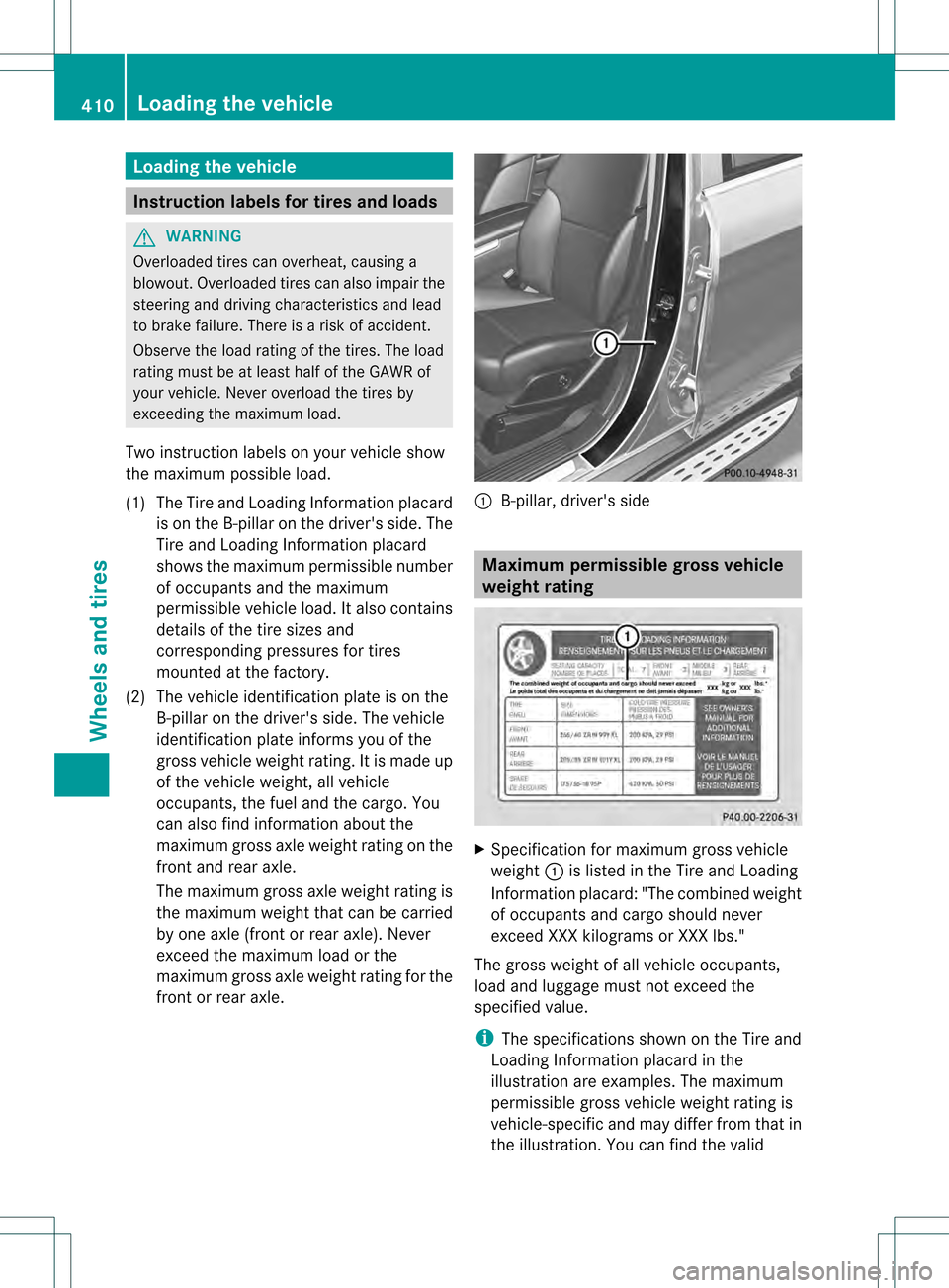
(1) The Tire and Loading Information placard is on the B-pillar on the driver's side. The
Tire and Loading Information placard
shows the maximum permissible number
of occupants and the maximum
permissible vehicle load. It also contains
details of the tire sizes and
corresponding pressures for tires
mounted at the factory.
(2) The vehicle identification plate is on the B-pillar on the driver's side. The vehicle
identification plate informs you of the
gross vehicle weight rating. It is made up
of the vehicle weight, all vehicle
occupants, the fuel and the cargo. You
can also find information about the
maximum gross axle weight rating on the
front and rear axle.
The maximum gross axle weight rating is
the maximum weight that can be carried
by one axle (front or rear axle). Never
exceed the maximum load or the
maximum gross axle weight rating for the
front or rear axle. 0002
B-pillar, driver's side Maximum permissible gross vehicle
weight rating
X
Specification for maximum gross vehicle
weight 0002is listed in the Tire and Loading
Information placard: "The combined weight
of occupants and cargo should never
exceed XXX kilograms or XXX lbs."
The gross weight of all vehicle occupants,
load and luggage must not exceed the
specified value.
i The specifications shown on the Tire and
Loading Information placard in the
illustration are examples. The maximum
permissible gross vehicle weight rating is
vehicle-specific and may differ from that in
the illustration.Y ou can find the valid410
Loading the vehicleWheels and tires
Page 413 of 458

maximu
mpermissible gross vehicle weight
rating for your vehicle on the Tire and
Loading Information placard. Number of seats
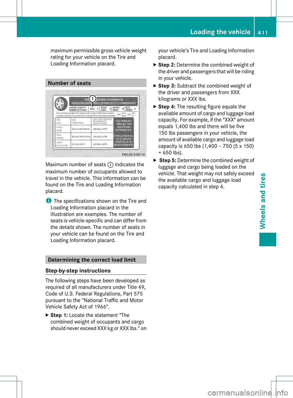
Maximum number of seats
0002indicates the
maximum number of occupants allowed to
travel in the vehicle. This information can be
found on the Tire and Loading Information
placard.
i The specifications shown on the Tire and
Loading Information placard in the
illustration are examples. The number of
seats is vehicle-specific and can differ from
the details shown. The number of seats in
your vehicle can be found on the Tire and
Loading Information placard. Determining the correct load limit
Step-by-step instructions The following steps have been developed as
required of all manufacturers under Title 49,
Code of U.S.F ederal Regulations, Part 575
pursuant to the "National Traffic and Motor
Vehicle Safety Act of 1966".
X Step 1: Locate the statement "The
combined weight of occupants and cargo
should never exceed XXX kg or XXX lbs." on your vehicle’s Tire and Loading Information
placard.
X Step 2: Determine the combined weight of
the driver and passengers that will be riding
in your vehicle.
X Step 3: Subtract the combined weight of
the driver and passengers from XXX
kilograms or XXX lbs.
X Step 4: The resulting figure equals the
available amount of cargo and luggage load
capacity. For example, if the "XXX" amount
equals 1,400 lbs and there will be five
150 lbs passengers in your vehicle, the
amount of available cargo and luggage load
capacity is 650 lbs (1,400 – 750 (5 x 150)
= 650 lbs).
X Step 5: Determine the combined weight of
luggage and cargo being loaded on the
vehicle. That weight may not safely exceed
the available cargo and luggage load
capacity calculated in step 4. Loading the vehicle
411Wheels and tires Z
Page 414 of 458

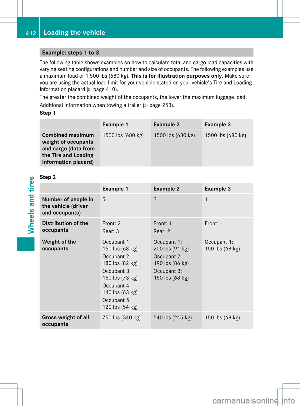
Example: steps 1 to 3
The following table shows examples on how to calculate total and cargo load capacities with
varying seating configurations and number and size of occupants. The following examples use
a maximum load of 1,500 lbs (680 kg). This is for illustration purposes only. Make sure
you are using the actual load limit for your vehicle stated on your vehicle's Tire and Loading
Information placard (Y page 410).
The greate rthe combined weight of the occupants, the lower the maximum luggage load.
Additional information when towing a trailer (Y page 253).
Step 1 Example 1 Example 2 Example 3
Combined maximum
weight of occupants
and cargo (data from
the Tire and Loading
Information placard)
1500 lbs (680 kg) 1500 lbs (680 kg) 1500 lbs (680 kg)
Step 2
Example 1 Example 2 Example 3
Number of people in
the vehicle (driver
and occupants)
5 3 1
Distribution of the
occupants
Front: 2
Rear: 3 Front: 1
Rear: 2 Front: 1
Weight of the
occupants
Occupant 1:
150 lbs (68 kg)
Occupant 2:
180 lbs (82 kg)
Occupant 3:
160 lbs (73 kg)
Occupant 4:
140 lbs (63 kg)
Occupant 5:
120 lbs (54 kg) Occupant 1:
200 lbs (91 kg)
Occupant 2:
190 lbs (86 kg)
Occupant 3:
150 lbs (68 kg) Occupant 1:
150 lbs (68 kg)
Gross weight of all
occupants
750 lbs (340 kg) 540 lbs (245 kg) 150 lbs (68 kg)412
Loading the vehicleWheels and tires
Page 415 of 458

Step 3
Example 1 Example 2 Example 3
Permissible load
(maximumg
ross
vehicle weight rating
from the Tire and
Loading Information
placard minus the
gross weight of all
occupants) 1500 lbs (680 kg)
0020750 lbs (340 kg) =
750 lbs (340 kg) 1500 lbs (680 kg)
0020540 lbs (245 kg) =
960 lbs (435 kg) 1500 lbs (680 kg)
0020150 lbs (68 kg) =
1350 lbs (612 kg)
Vehicle identification plate
Even if you have calculated the total cargo
carefully, you should still make sure tha tthe
gross vehicle weight rating and the gross axle
weight rating are not exceeded. Details can
be found on the vehicle identification plate on
the B-pillar on the driver's side of the vehicle
(Y page 410).
Permissible gross vehicle weight: the
gross weight of the vehicle, all passengers,
load and trailer load/noseweight (if
applicable) must not exceed the permissible
gross vehicle weight.
Gross axle weight rating: the maximum
permissible weight that can be carried by one
axle (front or rear axle).
To ensure that your vehicle does not exceed
the maximum permissible values (gross
vehicle weight and maximum gross axle
weight rating), have your loaded vehicle
(including driver, occupants, cargo, and full
trailer load if applicable) weighed on a
suitable vehicle weighbridge. Trailer load/noseweight
The trailer load/noseweight affects the gross
weight of the vehicle. If a trailer is attached,
the trailer load/noseweight is included in the
load along with occupants and luggage. The
trailer load/noseweight is usually
approximately 8% of the gross weight of the
trailer and its cargo. All about wheels and tires
Uniform Tire Quality Grading
Standards
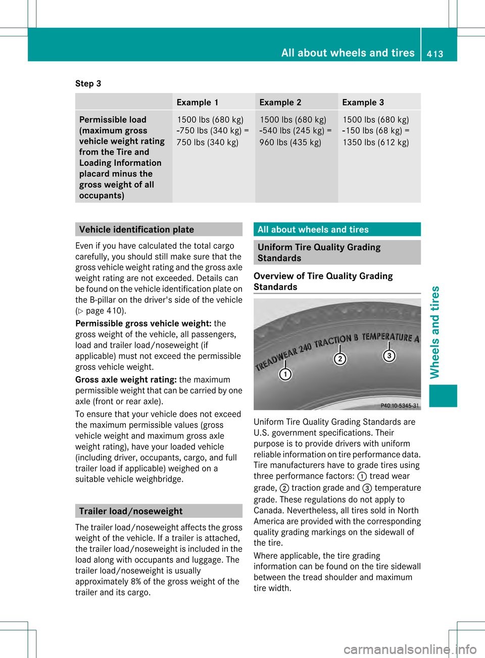
Overview of Tire Quality Grading
Standards Uniform Tire Quality Grading Standards are
U.S. government specifications. Their
purpose is to provide drivers with uniform
reliable information on tire performance data.
Tire manufacturers have to grade tires using
three performance factors:
0002tread wear
grade, 0003traction grade and 001Ftemperature
grade. These regulations do not apply to
Canada.N evertheless, all tires sold in North
America are provided with the corresponding
quality grading markings on the sidewall of
the tire.
Where applicable, the tire grading
information can be found on the tire sidewall
between the tread shoulder and maximum
tire width. All about wheels and tires
413Wheels and tires Z