2013 MERCEDES-BENZ GLK-CLASS SUV wheel
[x] Cancel search: wheelPage 359 of 380

X
Place the ratchet wrench onto the hexagon
nut of the jack so that the letters AB are
visible.
X Turn the ratchet wrench until the vehicle is
once again standing firmly on the ground.
X Place the jack to one side.
X Tighten the wheel bolts evenly in a
crosswise pattern in the sequence
indicated ( 0043 to 0083). The tightening
torque
must be 110 lb-ft (150 Nm).
X Turn the jack back to its initial position and
store it together with the rest of the tire-
change tool kit in the cargo compartment.
X Transport the faulty wheel in the cargo
compartment.
X Check the tire pressure of the newly
mounted wheel and adjust it if necessary.
Observe the recommended tire pressure
(Y page 331).
For further information on stowing the
collapsible spare wheel, see (Y page 361).
i Vehicles with tire pressure monitor: all
wheels mounted must be equipped with
functioning sensors. Wheel and tire combinations
General notes
! For safety reasons, Mercedes-Benz
recommends that you only use tires and
wheels which have been approved by
Mercedes-Benz specifically for your
vehicle. These tires have been specially adapted for
use with the control systems, such as ABS
or ESP
®
, and are marked as follows:
R MO = Mercedes-Benz Original
R MOE = Mercedes-Benz Original Extended
(tires featuring run-flat characteristics)
R MO1 = Mercedes-Benz Original (only
certain AMG tires)
Mercedes-Benz Original Extended tires
may
only be used on wheels that have been
specifically approved by Mercedes-Benz.
Only use tires, wheels or accessories
tested and approved by Mercedes-Benz.
Certain characteristics, e.g. handling,
vehicle noise emissions or fuel
consumption, may otherwise be adversely
affected. In addition, when driving with a
load, tire dimension variations could cause
the tires to come into contact with the
bodywork and axle components. This could
result in damage to the tires or the vehicle.
Mercedes-Benz accepts no liability for
damage resulting from the use of tires,
wheels or accessories other than those
tested and approved.
Information on tires, wheels and approved
combinations can be obtained from any
qualified specialist workshop.
! Retreaded tires are neither tested nor
recommended by Mercedes-Benz, since
previous damage cannot always be
detected on retreaded tires. As a result,
Mercedes-Benz cannot guarantee vehicle
safety if retreaded tires are mounted. Do
not mount used tires if you have no
information about their previous usage.
i The recommended pressures for various
operating conditions can be found:
R on the Tire and Loading Information
placard with the recommended tire
pressures on the B-pillar on the driver's
side
R in the tire pressure table on the inside of
the fuel filler flap Wheel and tire combinations
357
Wheels and tires Z
Page 360 of 380

Observe the notes on recommended tire
pressures under various operating
conditions (
Y page 331).
Check tire pressures regularly, and only
when the tires are cold. Comply with the
maintenance recommendations of the tire
manufacturer in the vehicle document
wallet.
i Notes on the vehicle equipment
– always
equip the vehicle with:
R tires of the same size on a given axle
(left/right)
R the same type of tires at a given time
(summer tires, winter tires, MOExtended
tires)
i On the following pages, you can find
information on approved wheel rims and
tire sizes for equipping your vehicle with
winter tires. Winter tires are not available
at the factory as standard equipment or
optional extras.
If you would like to equip your vehicle with
approved winter tires, you may also, in
certain circumstances, require rims of the
appropriate size. The size of the approved
winter tires may deviate from that of the
standard tires. This is dependent on the
model and the equipment installed at the
factory.
The tires and wheel rims, as well as further
information, can be obtained at a qualified
specialist workshop.
i Overview of abbreviations used in the
following tire tables:
R BA: both axles
R FA: front axle
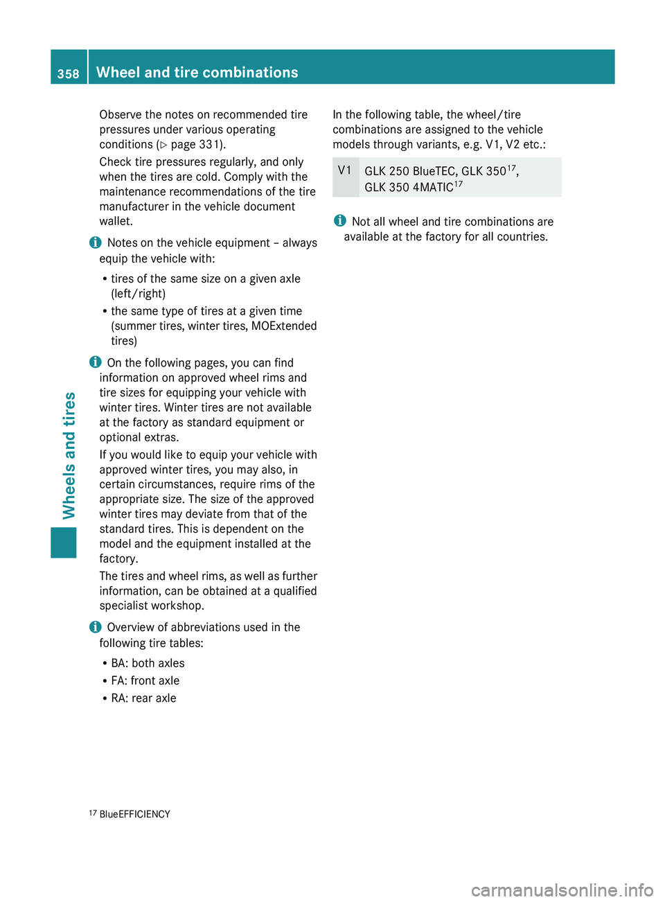
R RA: rear axle In the following table, the wheel/tire
combinations are assigned to the vehicle
models through variants, e.g. V1, V2 etc.: V1
GLK 250 BlueTEC, GLK 350
17
,
GLK 350 4MATIC 17 i
Not all wheel and tire combinations are
available at the factory for all countries.
17 BlueEFFICIENCY358
Wheel and tire combinations
Wheels and tires
Page 361 of 380

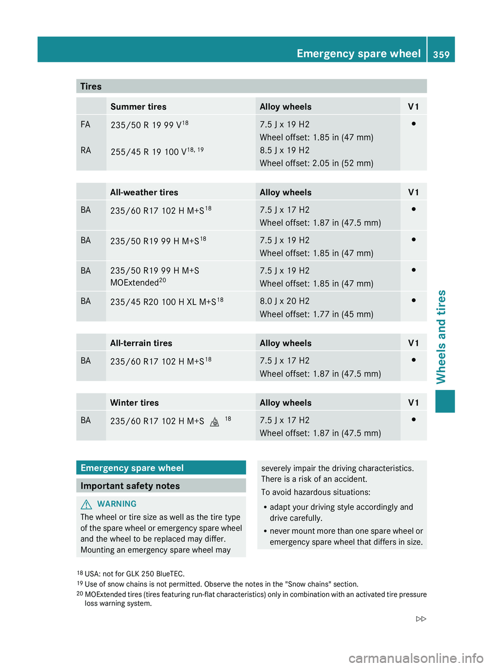
Tires
Summer tires Alloy wheels V1
FA
RA
235/50 R 19 99 V
18
255/45 R 19 100 V 18, 19 7.5 J x 19 H2
Wheel offset: 1.85 in (47 mm)
8.5 J x 19 H2
Wheel offset: 2.05 in (52 mm) 003B
All-weather tires Alloy wheels V1
BA
235/60 R17 102 H M+S
18 7.5 J x 17 H2
Wheel offset: 1.87 in (47.5 mm) 003B
BA
235/50 R19 99 H M+S
18 7.5 J x 19 H2
Wheel offset: 1.85 in (47 mm) 003B
BA 235/50 R19 99 H M+S
MOExtended
20 7.5 J x 19 H2
Wheel offset: 1.85 in (47 mm) 003B
BA
235/45 R20 100 H XL M+S
18 8.0 J x 20 H2
Wheel offset: 1.77 in (45 mm) 003B
All-terrain tires Alloy wheels V1
BA
235/60 R17 102 H M+S
18 7.5 J x 17 H2
Wheel offset: 1.87 in (47.5 mm) 003B
Winter tires Alloy wheels V1
BA
235/60 R17 102 H M+S
004D18 7.5 J x 17 H2
Wheel offset: 1.87 in (47.5 mm) 003B
Emergency spare wheel
Important safety notes
G
WARNING
The wheel or tire size as well as the tire type
of the spare wheel or
emergency spare wheel
and the wheel to be replaced may differ.
Mounting an emergency spare wheel may severely impair the driving characteristics.
There is a risk of an accident.
To avoid hazardous situations:
R
adapt your driving style accordingly and
drive carefully.
R never mount more than one
spare wheel or
emergency spare wheel that differs in size.
18 USA: not for GLK 250 BlueTEC.
19 Use of snow chains is not permitted. Observe the notes in the "Snow chains" section.
20 MOExtended tires (tires featuring run-flat
characteristics) only in combination with an activated tire pressure
loss warning system. Emergency spare wheel
359
Wheels and tires
Z
Page 362 of 380

R
only use a spare wheel or emergency spare
wheel of a different size briefly.
R do not switch ESP ®
off.
R have a spare wheel or emergency spare
wheel of a different size replaced at the
nearest qualified specialist workshop.
Observe that the wheel and tire dimensions
as well as the tire type must be correct.
When using an emergency spare wheel or
spare wheel of a different size, you must not
exceed the maximum speed of 50 mph
(80 km/h).
Snow chains must not be mounted on
emergency spare wheels. General notes
You should regularly check the pressure of
the emergency spare wheel, particularly
prior
to long trips, and correct the pressure as
necessary (Y page 331). The applicable value
is found on the wheel or under "Technical
data" ( Y page 357).
i When you are driving with the collapsible
spare wheel mounted, the tire pressure
loss warning system or the tire pressure
monitor cannot function reliably. Only
restart the tire pressure loss warning
system/the tire pressure monitor when the
damaged wheel has been replaced with a
new wheel.
Vehicles with tire pressure monitor:
after mounting an emergency spare wheel,
the system may still display the tire
pressure of the removed wheel for a few
minutes. The value displayed for the
mounted emergency spare wheel is not the
same as the current tire pressure of the
emergency spare wheel.
An emergency spare wheel may also be
mounted against the direction of rotation.
Observe the time restriction on use as well as
the speed limitation specified on the
emergency spare wheel. Replace the tires after six years at the latest,
regardless of wear. This also applies to the
emergency spare wheel.
Collapsible spare wheel
Removing the collapsible emergency
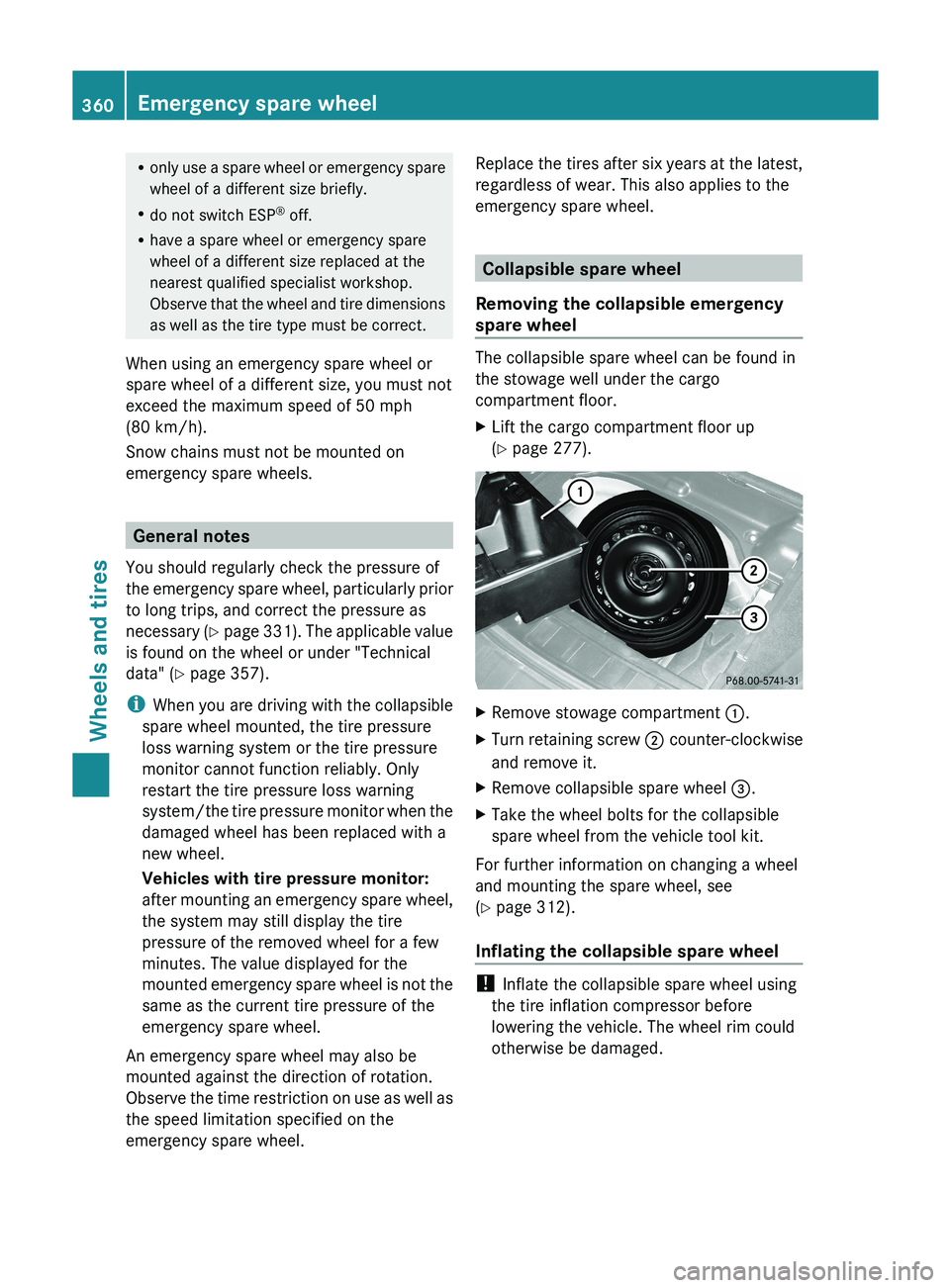
spare wheel The collapsible spare wheel can be found in
the stowage well under the cargo
compartment floor.
X
Lift the cargo compartment floor up
(Y page 277). X
Remove stowage compartment 0043.
X Turn retaining screw 0044 counter-clockwise
and remove it.
X Remove collapsible spare wheel 0087.
X Take the wheel bolts for the collapsible
spare wheel from the vehicle tool kit.
For further information on changing a wheel
and mounting the spare wheel, see
(Y page 312).
Inflating the collapsible spare wheel !
Inflate the collapsible spare wheel using
the tire inflation compressor before
lowering the vehicle. The wheel rim could
otherwise be damaged. 360
Emergency spare wheel
Wheels and tires
Page 363 of 380

X
Pull connector 0085 and the air hose out of
the housing.
X Remove the cap from the valve on the
collapsible spare wheel.
X Screw union nut 0043 on the air hose onto the
valve.
X Make sure on/off switch 0083 of the tire
inflation compressor is set to 0.
X Insert plug 0085 into the socket of the
cigarette lighter (Y
page 280) or into a 12 V
power socket (Y page 280) in your vehicle.
X Make sure that the SmartKey is in position
1(Y page 141) in the ignition lock.
X Press on/off switch 0083 on the tire inflation
compressor to I
.
The tire inflation compressor is switched
on. The tire is inflated. The tire pressure is
shown on pressure gauge 0087.
! Do not operate the tire inflation
compressor for longer than eight minutes
at a time without
a
break. It may otherwise
overheat.
The tire inflation compressor can be
operated again once it has cooled down.
X Inflate the tire to the specified tire
pressure.
The specified tire pressure is
printed on the
yellow label of the emergency spare wheel.
X When the specified tire pressure has been
reached, press on/off switch 0083 on the
electric air pump to 0.
The tire inflation compressor is switched
off. X
Turn the SmartKey to position 0 in the
ignition lock.
X If the tire pressure is higher than the
specified pressure, press pressure release
button 0044 until the correct tire
pressure has
been reached.
X Unscrew union nut 0043 on the air hose
from
the valve.
X Screw the cap onto the valve of the
collapsible spare wheel again.
X Stow plug 0085 and the air hose in the lower
section of the blower housing.
X Stow the tire inflation compressor in the
vehicle.
Stowing a used collapsible spare wheel Take the following steps to stow a used
collapsible spare wheel. Otherwise, the
collapsible spare wheel will
not
fit in the spare
wheel well. Mercedes-Benz recommends that
you have this work carried out at a qualified
specialist workshop.
! Only place the collapsible spare wheel in
the vehicle when it is dry. Otherwise,
moisture may get into the vehicle.
X Remove the valve extractor from the
vehicle tool kit.
X Unscrew the valve cap from the valve.
X Unscrew the valve insert from the valve and
release the air.
i Fully deflating the tires can take a few
minutes.
X Screw the valve insert back into the valve.
X Screw the valve cap back on.
X Place the valve extractor back into the
vehicle tool kit.
X Stow the collapsible spare wheel in the
emergency spare wheel well under the
cargo compartment and fasten in place. Emergency spare wheel
361
Wheels and tires Z
Page 364 of 380

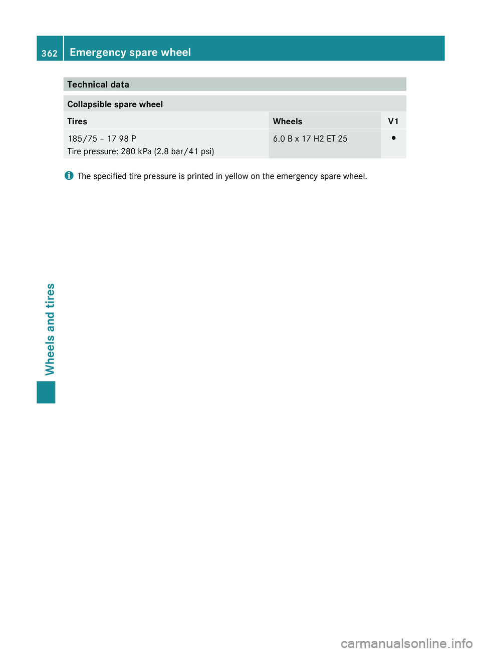
Technical data
Collapsible spare wheel
Tires Wheels V1
185/75 – 17 98 P
Tire pressure: 280 kPa (2.8 bar/41 psi) 6.0 B x 17 H2 ET 25 003B
i
The specified tire pressure is printed in yellow on the emergency spare wheel.362
Emergency spare wheelWheels and tires
Page 376 of 380

Dimensions and weights
Model 0043
Opening height 0044
Max.
headroom GLK 250
BlueTEC
4MATIC
82.2 in
(2087 mm) 77.0 in
(1955 mm) All other
models
82.1 in
(2086 mm) 76.9 in
(1954 mm) Missing values were not available at time of
going to print.
All models
Vehicle length
178.6 in (4536 mm)
Vehicle width
including exterior
mirrors
79.4 in (2016 mm)
Wheelbase
108.5 in (2755 mm)
Turning radius
38.2 ft (11.65 m)
Maximum roof load
GLK 250 BlueTEC
Vehicle height
66.7 in (1694 mm)
Ground clearance
8.0 in (204 mm) GLK 350
BlueEFFICIENCY
GLK 350 4MATIC
BlueEFFICIENCY
Vehicle height
66.7 in (1693 mm)
Ground clearance
8.2 in (208 mm)
Trailer tow hitch
Mounting dimensions
! If you have a trailer tow hitch retrofitted,
changes to the engine cooling system and
drive train may be necessary,
depending on
the vehicle type. Anchorage points for the trailer tow hitch
(example)
0043
Anchorage points
0044 Rear axle center line Trailer loads
Missing values were not available at time of
going to print. 374
Trailer tow hitch
Technical data