Page 221 of 454

Rear sensors
Center Approx. 48in (approx.
120cm)
Corners Approx. 32in (approx.
80cm)
Minimum distance
Center Approx. 8in (approx. 20cm)
Corners Approx. 6in (approx. 15cm)
If there is an obstacle within this range, the
relevant warning displays light up and a
warning tone sounds. If the distance falls
below the minimum, the distance may no
longer be shown.
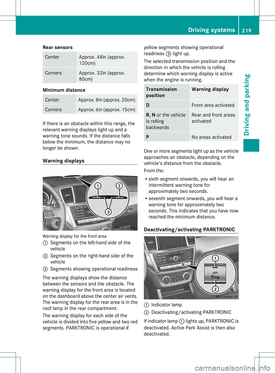
Warning displays Warning display for the front area
0002
Segments on the left-hand side of the
vehicle
0003 Segments on the right-hand side of the
vehicle
0021 Segments showing operational readiness
The warning displays show the distance
between the sensors and the obstacle. The
warning display for the front area is located
on the dashboard above the center ai rvents.
The warning display for the rear area is in the
roof lamp in the rear compartment.
The warning display for each side of the
vehicle is divided into five yellow and two red
segments. PARKTRONIC is operational if yellow segments showing operational
readiness 0021light up.
The selected transmission position and the
direction in which the vehicle is rolling
determine which warning display is active
when the engine is running. Transmission
position Warning display
D
Front area activated
R,
Nor the vehicle
is rolling
backwards Rear and front areas
activated P
No areas activated
One or more segments light up as the vehicle
approaches an obstacle, depending on the
vehicle's distance from the obstacle.
From the:
R
sixth segmen tonwards, you will hea ran
intermittent warning ton efor
approximately two seconds.
R seventh segment onwards, you will hear a
warning tone for approximately two
seconds. This indicates that you have now
reached the minimum distance.
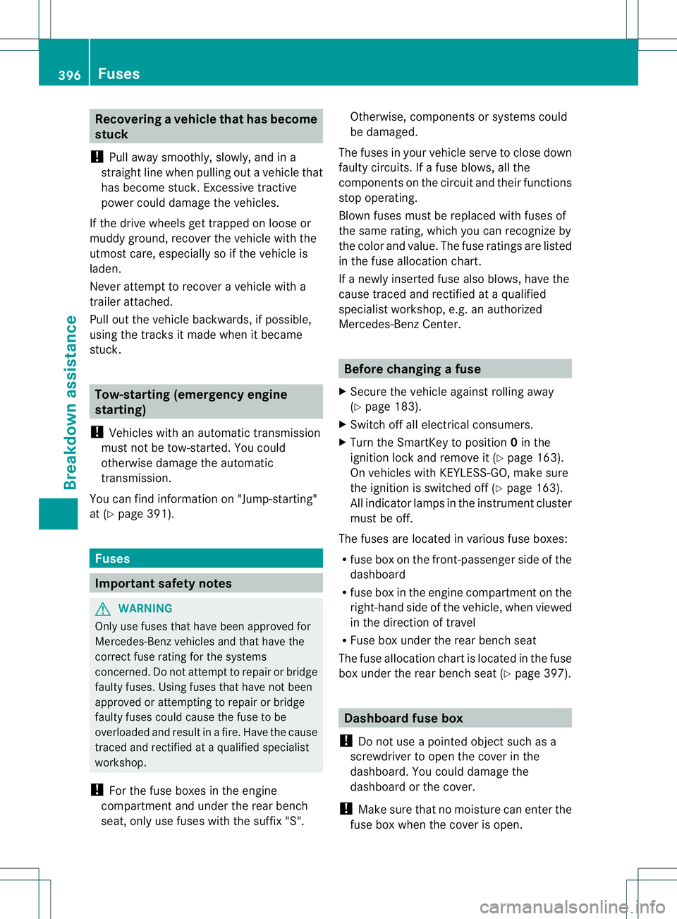
Deactivating/activating PARKTRONIC 0002
Indicator lamp
0003 Deactivating/activating PARKTRONIC
If indicator lamp 0002lights up, PARKTRONIC is
deactivated. Active Park Assist is then also
deactivated. Driving systems
219Driving and parking Z
Page 398 of 454

Recovering
avehicle that has become
stuck
! Pull away smoothly, slowly, and in a
straigh tline when pulling out a vehicle that
has become stuck. Excessive tractive
power could damage the vehicles.
If the drive wheels get trapped on loose or
muddy ground, recover the vehicle with the
utmost care, especially so if the vehicle is
laden.
Never attempt to recover a vehicle with a
trailer attached.
Pull out the vehicle backwards, if possible,
using the tracks it made when it became
stuck. Tow-starting (emergency engine
starting)
! Vehicles with an automatic transmission
must not be tow-started. You could
otherwise damage the automatic
transmission.
You can find information on "Jump-starting"
at (Y page 391). Fuses
Important safety notes
G
WARNING
Only use fuses that have been approved for
Mercedes-Ben zvehicles and that have the
correct fuse rating for the systems
concerned. Do not attempt to repair or bridge
faulty fuses. Using fuses that have not been
approved or attempting to repair or bridge
faulty fuses could cause the fuse to be
overloaded and result in afire. Have the cause
traced and rectified at a qualified specialist
workshop.
! For the fuse boxes in the engine
compartment and under the rear bench
seat, only use fuses with the suffix "S". Otherwise, components or systems could
be damaged.
The fuses in your vehicle serve to close down
faulty circuits. If afuse blows, all the
components on the circuit and their functions
stop operating.
Blown fuses must be replace dwith fuses of
the same rating, which you can recognize by
the color and value. The fuse ratings are listed
in the fuse allocation chart.
If a newly inserted fuse also blows, have the
cause traced and rectified at a qualified
specialist workshop, e.g. an authorized
Mercedes-Ben zCenter. Before changing a fuse
X Secure the vehicle against rolling away
(Y page 183).
X Switch off all electrical consumers.
X Turn the SmartKey to position 0in the
ignition lock and remove it (Y page 163).
On vehicles with KEYLESS-GO, make sure
the ignition is switched off (Y page 163).
All indicator lamps in the instrument cluster
must be off.
The fuses are located in various fuse boxes:
R fuse box on the front-passenger side of the
dashboard
R fuse box in the engine compartment on the
right-hand side of the vehicle, when viewed
in the direction of travel
R Fuse box under the rear bench seat
The fuse allocation chart is located in the fuse
box under the rear bench seat (Y page 397). Dashboard fuse box
! Do not use a pointed objec tsuch as a
screwdriver to open the cover in the
dashboard. You could damage the
dashboard or the cover.
! Make sure that no moisture can ente rthe
fuse box when the cover is open. 396
FusesBreakdown assistance
Page 399 of 454

!
When closing the cover, make sure that it
is lying correctly on the fuse box. Moisture
seeping in or dirt could otherwise impair
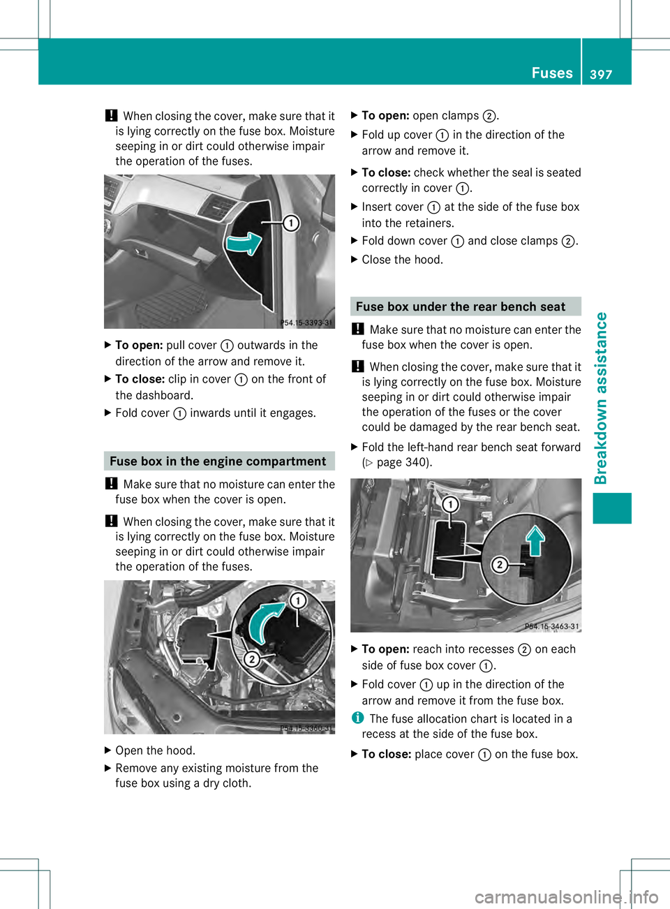
the operation of the fuses. X
To open: pull cover 0002outwards in the
direction of the arrow and remove it.
X To close: clip in cover 0002on the front of
the dashboard.
X Fold cover 0002inwards until it engages. Fuse box in the engine compartment
! Make sure that no moisture can enter the
fuse box when the cover is open.
! When closing the cover, make sure that it
is lying correctly on the fuse box. Moisture
seeping in or dirt could otherwise impair
the operation of the fuses. X
Open the hood.
X Remove any existing moisture from the
fuse box using a dry cloth. X
To open: open clamps 0003.
X Fold up cover 0002in the direction of the
arrow and remove it.
X To close: check whether the seal is seated
correctly in cover 0002.
X Insert cover 0002at the side of the fuse box
into the retainers.
X Fold down cover 0002and close clamps 0003.
X Close the hood. Fuse box under the rear bench seat
! Make sure that no moisture can enter the
fuse box when the cover is open.
! When closing the cover, make sure that it
is lying correctly on the fuse box. Moisture
seeping in or dirt could otherwise impair
the operation of the fuses or the cover
could be damaged by the rear bench seat.
X Fold the left-hand rear bench seat forward
(Y page 340). X
To open: reach into recesses 0003on each
side of fuse box cover 0002.
X Fold cover 0002up in the direction of the
arrow and remove it from the fuse box.
i The fuse allocation chart is located in a
recess at the side of the fuse box.
X To close: place cover 0002on the fuse box. Fuses
397Breakdown assistance Z