2013 MERCEDES-BENZ G-CLASS SUV ECU
[x] Cancel search: ECUPage 313 of 364
If the vehicle has to be towed more than
30 miles (
50km),
the entire vehicle must be
raised and transported.
! Only secure the tow cable or tow bar to
the towing eyes. You could otherwise
damage the vehicle.
! Do not tow with sling-type equipment.
This could damage the vehicle.
! Do not use the towing eyes for recovery
purposes as this could damage the vehicle.
If in doubt, recover the vehicle with a crane.
! When towing, pull away slowly and
smoothly. If the tractive power is too high,
the vehicles could be damaged.
! Your vehicles is equipped with an
automatic transmission. Therefore, you
must not have the vehicle tow-started. The
transmission may otherwise be damaged. G
WARNING
If the weight of the vehicle to be towed or tow-
started is greater than the permissible gross
weight of your vehicle:
R the towing eye could detach itself
R the vehicle/trailer combination could
rollover.
There is a risk of an accident.
When towing or tow-starting another vehicle,
its weight should not be greater than the
permissible gross weight of your vehicle.
Information on your vehicle's gross vehicle
weight rating can be found on the vehicle
identification plate ( Y page 349).
It is better to have the vehicle transported
than to have it towed.
If the transfer case
can be shifted into neutral
N, you can tow the vehicle. If the transfer case cannot be shifted into
neutral N, you can tow the vehicle with one
axle raised. Please
bear
the following in mind:
R remove the propeller shaft between the
transfer case and the rolling axle.
R turn the SmartKey to position 1 in the
ignition lock (Y page 139).
The battery must be connected and charged.
Otherwise, you:
R cannot turn the SmartKey in the ignition
lock to position 2(Y page 139)
R cannot shift the automatic transmission to
position N
i Deactivate the automatic locking feature
(Y page 75). You could otherwise be locked
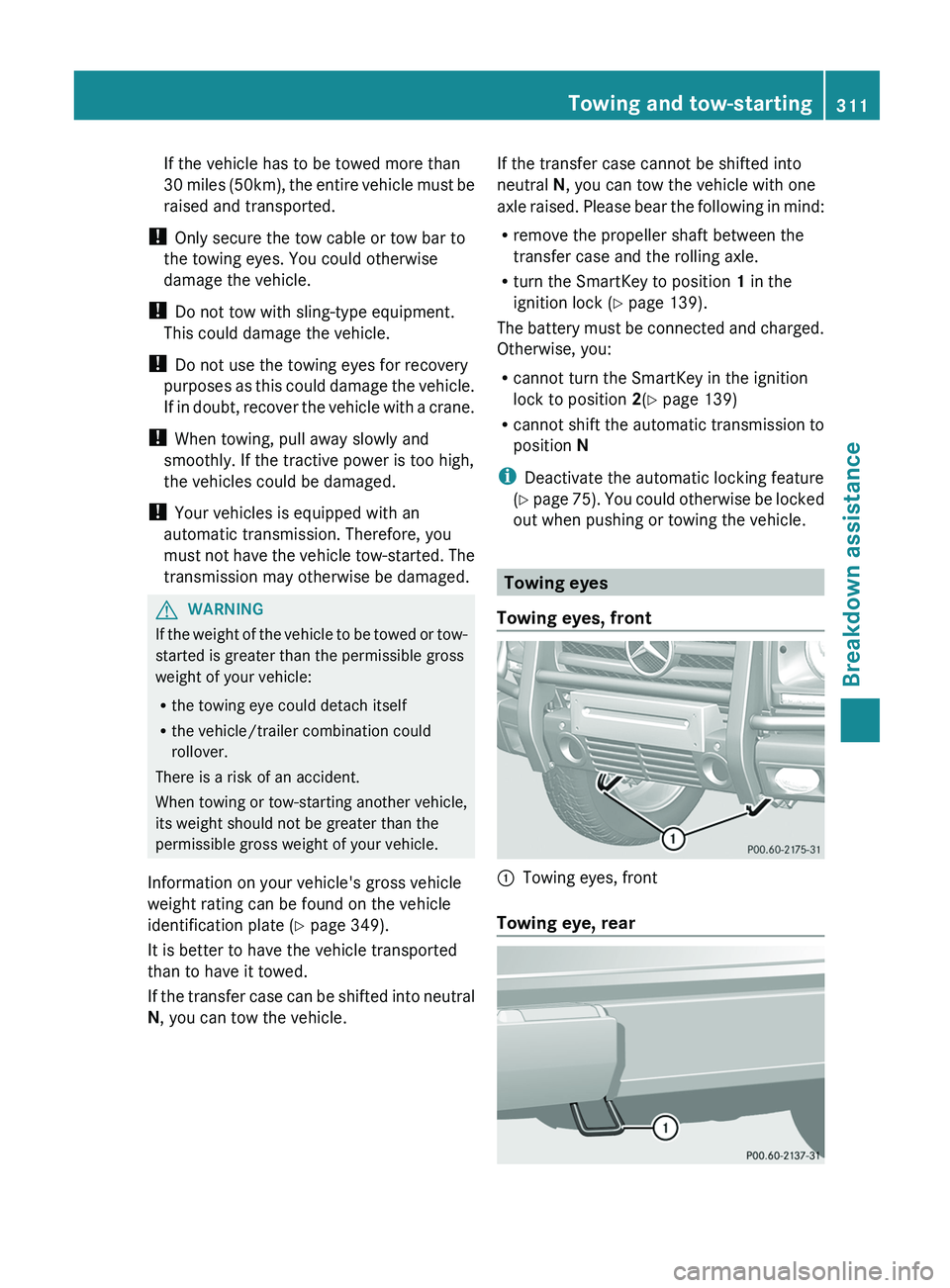
out when pushing or towing the vehicle. Towing eyes
Towing eyes, front 0043
Towing eyes, front
Towing eye, rear Towing and tow-starting
311
Breakdown assistance Z
Page 314 of 364
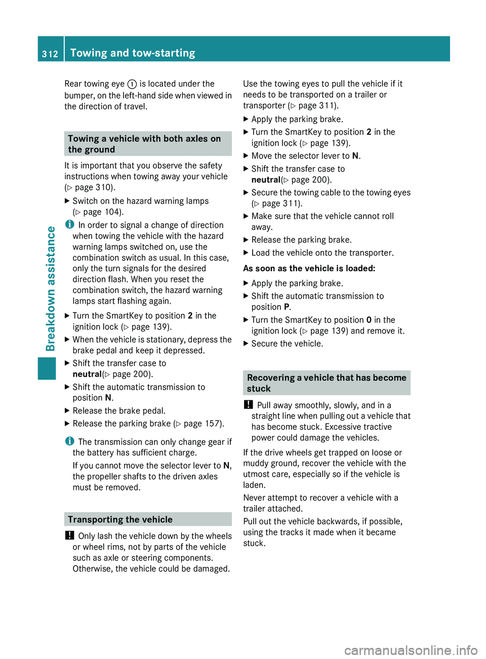
Rear towing eye
0043 is located under the
bumper, on the left-hand
side when viewed in
the direction of travel. Towing a vehicle with both axles on
the ground
It is important that you observe the safety
instructions when towing away your vehicle
(Y page 310).
X Switch on the hazard warning lamps
(Y page 104).
i In order to signal a change of direction
when towing the vehicle with the hazard
warning lamps switched on, use the
combination switch as usual. In this case,
only the turn signals for the desired
direction flash. When you reset the
combination switch, the hazard warning
lamps start flashing again.
X Turn the SmartKey to position 2 in the
ignition lock (Y page 139).
X When the vehicle is stationary, depress the
brake pedal and keep it depressed.
X Shift the transfer case to
neutral (Y page 200).
X Shift the automatic transmission to
position N.
X Release the brake pedal.
X Release the parking brake ( Y page 157).
i The transmission can only change gear if
the battery has sufficient charge.
If you cannot move
the selector lever to N,
the propeller shafts to the driven axles
must be removed. Transporting the vehicle
! Only lash the vehicle
down by the wheels
or wheel rims, not by parts of the vehicle
such as axle or steering components.
Otherwise, the vehicle could be damaged. Use the towing eyes to pull the vehicle if it
needs to be transported on a trailer or
transporter (
Y page 311).
X Apply the parking brake.
X Turn the SmartKey to position 2 in the
ignition lock (Y page 139).
X Move the selector lever to N.
X Shift the transfer case to
neutral (Y page 200).
X Secure the towing cable to the towing eyes
(Y page 311).
X Make sure that the vehicle cannot roll
away.
X Release the parking brake.
X Load the vehicle onto the transporter.
As soon as the vehicle is loaded:
X Apply the parking brake.
X Shift the automatic transmission to
position P.
X Turn the SmartKey to position 0 in the
ignition lock (Y page 139) and remove it.
X Secure the vehicle. Recovering a vehicle that has become
stuck
! Pull away smoothly, slowly, and in a
straight line when pulling
out a vehicle that
has become stuck. Excessive tractive
power could damage the vehicles.
If the drive wheels get trapped on loose or
muddy ground, recover the vehicle with the
utmost care, especially so if the vehicle is
laden.
Never attempt to recover a vehicle with a
trailer attached.
Pull out the vehicle backwards, if possible,
using the tracks it made when it became
stuck. 312
Towing and tow-starting
Breakdown assistance
Page 315 of 364
Towing in the event of malfunctions
General notes !
If you are removing the propeller shaft,
use M10 nuts as spacers on the M8 bolts
and secure them with M8 nuts.
New self-locking nuts must be used when
the propeller shafts are refitted.
X Observe the safety notes as you do so
(Y page 310).
i Consult an authorized Mercedes-Benz
Center.
Engine damage, gear damage or
electrical malfunctions X
Move the selector lever to
position N(Y page 145).
X Shift the transfer case to
neutral (Y page 200).
In the event of damage to the transfer
case Have the propeller shafts between the axles
and the transfer case removed.
In the event
of
damage to the front axleHave the propeller shaft between the rear
axle and the transfer case removed.
Have the vehicle towed with the front axle
raised.
In the event of damage to the rear axle
Have the propeller shaft between the front
axle and the transfer case removed.
Have the vehicle towed with the rear axle
raised and with wheel rollers under the front
axle. Fuses
Important safety notes
G
WARNING
Only use fuses that have been approved for
Mercedes-Benz vehicles and that have the
correct fuse rating for the systems
concerned. Do not attempt
to repair or bridge
faulty fuses. Using fuses that have not been
approved or attempting to repair or bridge
faulty fuses could cause the fuse to be
overloaded and result in a fire. Have the cause
traced and rectified at a qualified specialist
workshop.
! Only use fuses that have been approved
for Mercedes-Benz vehicles and which
have the correct fuse rating for the system
concerned. Otherwise, components or
systems could be damaged.
The fuses in your vehicle serve to close down
faulty circuits. If a fuse blows, all the
components on the circuit and their functions
stop operating.
Blown fuses must be replaced with fuses of
the same rating, which you can recognize by
the color and value. The fuse ratings are listed
in the fuse allocation chart.
i If a fuse has blown, contact a breakdown
service or an authorized Mercedes-Benz
Center.
If a newly inserted fuse also blows, have the
cause traced and rectified at a qualified
specialist workshop, e.g. an authorized
Mercedes-Benz Center. Before changing a fuse
X Park the vehicle and apply the parking
brake.
X Switch off all electrical consumers.
X Remove the SmartKey from the ignition
lock.
All indicator lamps in
the instrument cluster
must be off. Fuses
313
Breakdown assistance Z
Page 327 of 364
Never exceed the maximum permissible tire
inflation pressure. Always observe the
recommended tire pressure for your vehicle
when adjusting the tire pressure
(Y page 338).
i
The actual values for tires are vehicle-
specific and may deviate
from the values in
the illustration. Checking the tire pressures
Important safety notes Observe the notes on tire pressure
(Y page 322).
Information on air pressure for the tires on
your vehicle can be found:
R
on the vehicle's Tire and Loading
Information placard on the B-pillar
(Y page 322)
R on the tire pressure label on the fuel filler
flap ( Y page 322)
R in the "Tire pressure information" section
R in the "Tire pressure information" section
(Y page 322)
Checking tire pressures manually To determine and set the correct tire
pressure, proceed as follows:
X
Remove the valve cap of the tire that is to
be checked.
X Press the tire pressure gauge securely onto
the valve.
X Read the tire pressure and compare it with
the recommended value on the Tire and
Loading Information
placard on
the B-pillar
on the driver's side of your vehicle
(Y page 322).
X The tire pressure is too low: increase the
tire pressure to the recommended value.
X The tire
pressure is too high: press down
the metal
pin in the valve using the tip of a
pen, for example.
Air is released from the tire. X
Check the tire pressure again with the tire
pressure gauge.
X Screw the valve cap onto the valve.
X Repeat these steps for the other tires. Tire pressure monitor
Important safety notes G
WARNING
Each tire, including the spare (if provided),
should be checked at least once a month
when cold and inflated to the pressure
recommended by the vehicle manufacturer
on the Tire and Loading Information placard
on the driver's door B-pillar or the tire
pressure label on the inside of the fuel filler
flap. If your vehicle
has tires of a different size
than the size indicated on the Tire and Loading
Information placard or the tire pressure label,
you should determine the proper tire pressure
for those tires.
As an added safety feature, your vehicle has
been equipped with a tire pressure monitoring
system (TPMS) that illuminates a low tire
pressure telltale when one or more of your
tires are significantly underinflated.
Accordingly, when the low tire pressure
telltale illuminates, you should stop and check
your tires as soon as possible, and inflate
them to the proper pressure. Driving on a
significantly underinflated tire causes the tire
to overheat and can lead to tire failure.
Underinflation also reduces fuel efficiency
and tire tread life, and may affect the vehicle's
handling and stopping ability.
Please note that the TPMS is not a substitute
for proper tire maintenance, and it is the
driver's responsibility to maintain correct tire
pressure, even if underinflation has not
reached the level to trigger illumination of the
TPMS low tire pressure telltale.
USA only:
Your vehicle has also been equipped with a
TPMS malfunction indicator to indicate if the
system is not operating properly. The TPMS Tire pressure
325
Wheels and tires
Z
Page 342 of 364
Bead
The tire bead ensures that the tire sits
securely on the
wheel.
There are several steel
wires in the bead to prevent the tire from
coming loose from the wheel rim.
Sidewall The part of the tire between the tread and the
bead.
Weight of optional extras
The combined weight of those optional extras
that weigh more than the replaced standard
parts and more than 2.3 kg (5 lbs). These
optional extras, such as high-performance
brakes, level control, a roof rack or a high-
performance battery, are not included in the
curb weight and the weight of the
accessories.
TIN (Tire Identification Number) This is a unique identifier which can be used
by a tire manufacturer to identify tires, for
example for a
product
recall, and thus identify
the purchasers. The TIN is made up of the
manufacturer's identity code, tire size, tire
type code and the manufacturing date.
Load bearing index The load bearing index (also load index) is a
code
that
contains the
maximum load bearing
capacity of a tire.
Traction Traction is the result of friction between the
tires and the road surface.
TWR (Tongue Weight Rating)
The TWR specifies the maximum permissible
weight that the
ball
coupling of the trailer tow
hitch can support. Treadwear indicators Narrow bars (tread wear bars) that are
distributed over the
tire
tread. If the tire tread
is level with the bars, the wear limit of 00CD in
(1.6 mm) has been reached.
Occupant distribution The distribution of occupants in a vehicle at
their designated seating positions.
Total load limit
Nominal load and luggage load plus 150 lbs
(68 kg) multiplied by the number of seats in
the vehicle.
Changing a wheel
Flat tire
The "Breakdown assistance" section
(Y page 304)
contains
information and notes
on how to deal with a flat tire. Interchanging the wheels
G
WARNING
Rotate front and rear wheels only if the tires
are of the same dimension.
If your vehicle is equipped with mixed-size
tires (different tire dimensions
front vs. rear),
tire rotation is not possible. G
WARNING
Have the tightening torque checked after
changing a wheel. The wheels could come
loose if they are not tightened to a torque of
96 lb-ft (130 Nm).
Only use genuine
Mercedes-Benz wheel bolts
specified for your vehicle's rims.
! On vehicles equipped with a tire pressure
monitor, electronic components are
located in the wheel. 340
Changing a wheel
Wheels and tires
Page 343 of 364
Tire-mounting tools should not be used
near the valve. This could damage the
electronic components.
Only have tires changed at a qualified
specialist workshop.
Interchanging the front and rear wheels of
differing dimensions can render the general
operating permit invalid.
Always pay attention to the instructions and
safety notices in the section on "Changing a
wheel and mounting a spare wheel"
(Y page 341).
The wear patterns on the front and rear tires
differ, depending on the
operating conditions.
Rotate the wheels before a clear wear pattern
has formed on the tires. Front tires typically
wear more on the shoulders and the rear tires
in the center.
If your vehicle's tire configuration allows, you
can rotate the wheels according to the
intervals in the tire manufacturer's warranty
book in your vehicle documents. If no
warranty book is available, the tires should be
replaced every 3000 to
6000 miles(5000 to 10,000 km), or earlier if
tire wear necessitates it. Do not change the
direction of wheel rotation.
Clean the contact surfaces of the wheel and
the brake disc thoroughly every time a wheel
is interchanged. Check the tire pressure and
reactivate the tire pressure monitor
(Y page 325) if necessary. Direction of rotation
Tires with a specified direction of rotation
have additional benefits, e.g.
if there is a risk
of hydroplaning. You will only gain these
benefits if the correct direction of rotation is
observed.
An arrow on the sidewall of the tire indicates
its correct direction of rotation.
You may mount the spare wheel against the
direction of rotation. Adhere to the time
restriction on use as well as the speed
limitation specified on the spare wheel. Storing wheels
Store tires that are not being used in a cool,
dry and preferably dark place. Protect the
tires from oil, grease, gasoline and diesel. Cleaning the wheels
G
WARNING
Do not use power washers with circular-jet
nozzles (dirt grinders) to
clean your vehicle, in
particular the tires. You could otherwise
damage the tires and cause an accident. Mounting a wheel
Preparing the vehicle G
WARNING
You must remove the spare wheel from the
spare wheel carrier before lifting the vehicle.
Otherwise the vehicle could fall off the jack
and injure you or others.
X Prepare the vehicle as described
(Y page 304).
X Remove the vehicle tool kit and the jack
(Y page 302).
X Secure the vehicle to prevent it from rolling
away.
X Remove the spare wheel from the spare
wheel bracket ( Y page 303).
i Vehicles without a spare wheel or
emergency spare wheel are not equipped
with a tire-change tool
kit at the factory. For
more information on which tools are
required to perform a wheel change on your
vehicle e.g. lug wrench or jack, consult an
authorized Mercedes-Benz Center.
Securing the vehicle to prevent it from
rolling away X
On level ground: place chocks or other
suitable items under the front and rear of Changing a wheel
341
Wheels and tires Z
Page 344 of 364
the wheel that is diagonally opposite the
wheel you wish to change.
X On downhill gradients: place chocks or
other suitable items in front of the wheels
of the front and rear axle.
Raising the vehicle G
WARNING
If you do not position the jack correctly at the
appropriate jacking point of the vehicle, the
jack could tip over with the vehicle raised.
There is a risk of injury.
Only position the jack at the appropriate
jacking point of the vehicle. The base of the
jack must be positioned vertically, directly
under the jacking point of the vehicle.
! The jack is designed exclusively for
jacking up the vehicle
at the jacking points.
Otherwise, your vehicle could be damaged.
The following must be observed when raising
the vehicle:
R to raise the vehicle, only use the vehicle-
specific jack that has been tested and
approved by Mercedes-Benz. If used
incorrectly, the jack could tip over with the
vehicle raised.
R the jack is designed only to raise and hold
the vehicle for a short time while a wheel
is being changed. It is not suited for
performing maintenance work under the
vehicle.
R avoid changing the wheel on uphill and
downhill slopes.
R before raising the vehicle, secure it from
rolling away by applying the parking brake
and inserting wheel chocks. Never
disengage the parking brake while the
vehicle is raised.
R the jack must be placed on a firm, flat and
non-slip surface. On a loose surface, a
large, load-bearing underlay must be used.
On a slippery surface, a non-slip underlay
must be used, e.g. rubber mats. R
do not use wooden blocks or similar
objects as a jack underlay. Otherwise, the
jack will not be able to achieve its load-
bearing capacity due to the restricted
height.
R make sure that the distance between the
underside of the tires
and the ground does
not exceed 1.2 inches (3 cm).
R never place your hands and feet under the
raised vehicle.
R never lie under the raised vehicle.
R never start the engine when the vehicle is
raised.
R never open or close a door or the tailgate
when the vehicle is raised.
R make sure that no persons are present in
the vehicle when the vehicle is raised. X
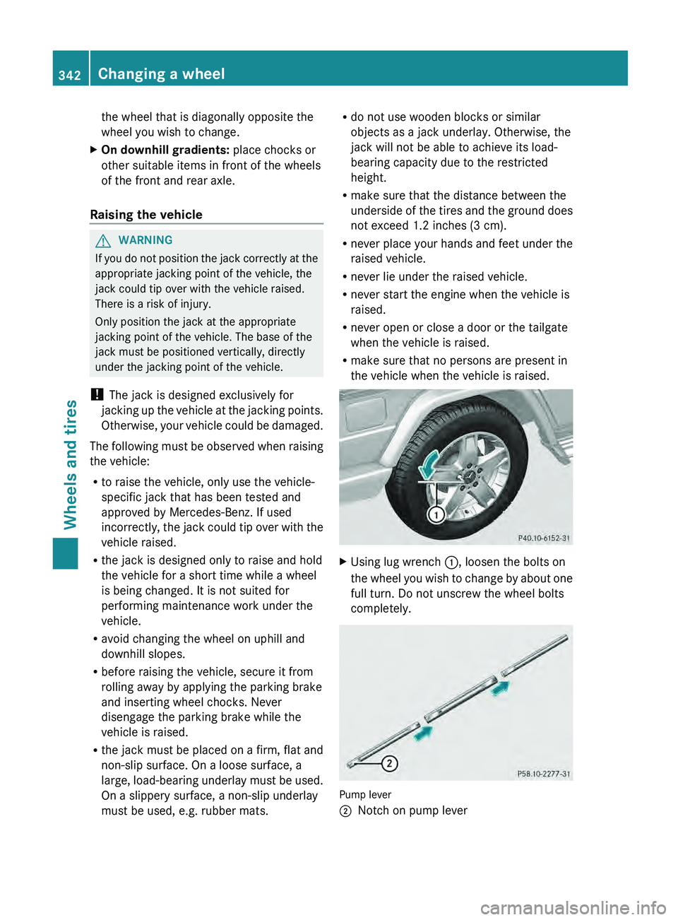
Using lug wrench 0043, loosen the bolts on
the wheel you wish
to change by about one
full turn. Do not unscrew the wheel bolts
completely. Pump lever
0044
Notch on pump lever342
Changing a wheel
Wheels and tires
Page 345 of 364
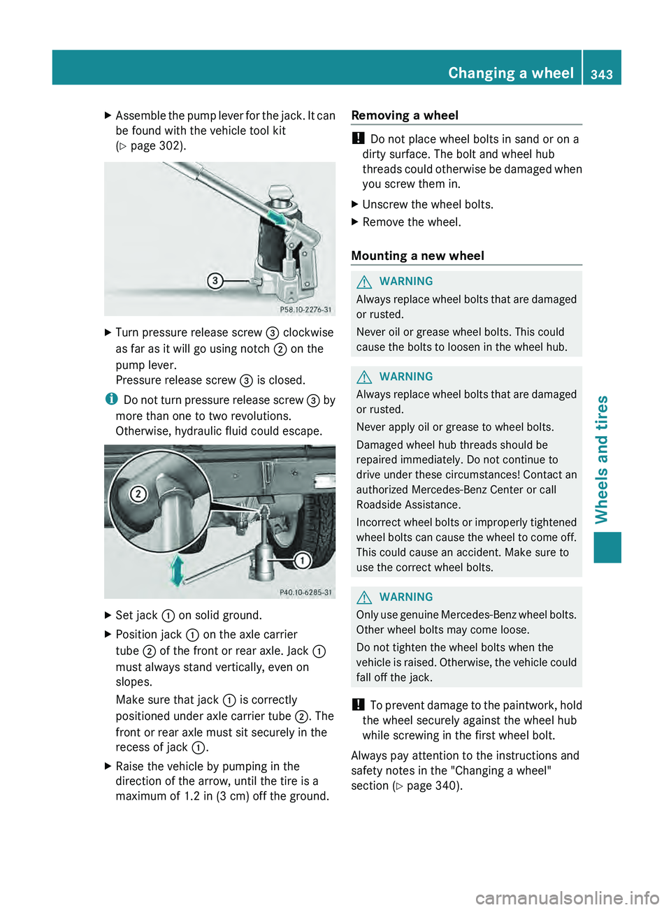
X
Assemble the pump lever for the jack. It can
be found with the vehicle tool kit
(Y page 302). X
Turn pressure release screw 0087 clockwise
as far as it will go using notch 0044 on the
pump lever.
Pressure release screw 0087 is closed.
i Do not turn
pressure
release screw 0087 by
more than one to two revolutions.
Otherwise, hydraulic fluid could escape. X
Set jack 0043 on solid ground.
X Position jack 0043 on the axle carrier
tube 0044 of the front or rear axle. Jack 0043
must always stand vertically, even on
slopes.
Make sure that jack 0043 is correctly
positioned under axle carrier tube 0044. The
front or rear axle must sit securely in the
recess of jack 0043.
X Raise the vehicle by pumping in the
direction of the arrow, until the tire is a
maximum of 1.2 in (3 cm ) off the ground.Removing a wheel !
Do not place wheel bolts in sand or on a
dirty surface. The bolt and wheel hub
threads could otherwise be
damaged when
you screw them in.
X Unscrew the wheel bolts.
X Remove the wheel.
Mounting a new wheel G
WARNING
Always replace wheel bolts that are damaged
or rusted.
Never oil or grease wheel bolts. This could
cause the bolts to loosen in the wheel hub. G
WARNING
Always replace wheel bolts that are damaged
or rusted.
Never apply oil or grease to wheel bolts.
Damaged wheel hub threads should be
repaired immediately. Do not continue to
drive under these circumstances! Contact an
authorized Mercedes-Benz Center or call
Roadside Assistance.
Incorrect wheel bolts or
improperly tightened
wheel bolts can cause the wheel to come off.
This could cause an accident. Make sure to
use the correct wheel bolts. G
WARNING
Only use genuine Mercedes-Benz wheel bolts.
Other wheel bolts may come loose.
Do not tighten the wheel bolts when the
vehicle is raised. Otherwise,
the vehicle could
fall off the jack.
! To prevent damage to the paintwork, hold
the wheel securely against the wheel hub
while screwing in the first wheel bolt.
Always pay attention to the instructions and
safety notes in the "Changing a wheel"
section ( Y page 340). Changing a wheel
343
Wheels and tires Z