Page 309 of 373
Useful information
i This Owner's Manual describes all mod-
els, series and optional equipment for your
vehicle that were available at the time of
going to press. National variations are pos- sible. Note that your vehicle may not be
equipped with all of the functions descri-
bed. This is also the case for systems and
functions relevant to safety.
i Read the information on qualified special-
ist workshops: (Y page 24). Where will I find...?
Warning triangle
Removing/replacing the warning trian-
gle X
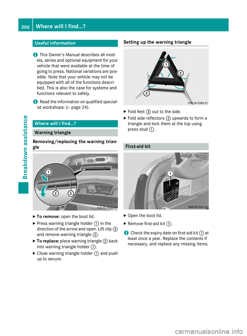
To remove: open the boot lid.
X Press warning triangle holder :in the
direction of the arrow and open. Lift clip =
and remove warning triangle ;.
X To replace: place warning triangle ;back
into warning triangle holder :.
X Close warning triangle holder :and push
up to secure. Setting up the warning triangle X
Fold feet =out to the side.
X Fold side reflectors ;upwards to form a
triangle and lock them at the top using
press stud :. First-aid kit
X
Open the boot lid.
X Remove first-aid kit :.
i Check the expiry date on first-aid kit
:at
least once a year. Replace the contents if
necessary, and replace any missing items. 306
Where will I find...?Breakdown assistance
Page 310 of 373
Fire extinguisher
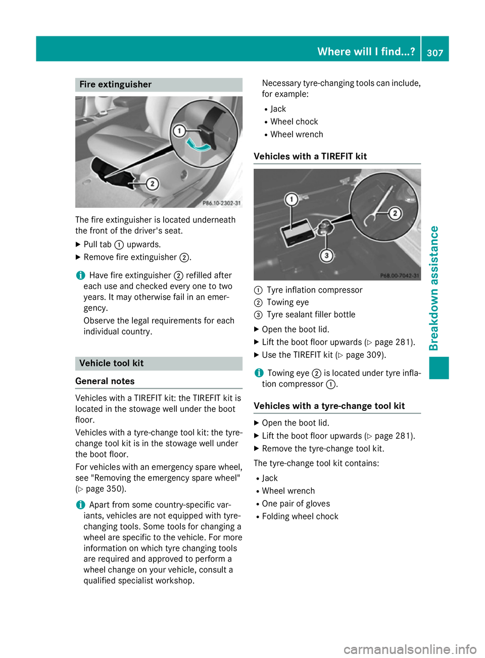
The fire extinguisher is located underneath
the front of the driver's seat.
X Pull tab :upwards.
X Remove fire extinguisher ;.
i Have fire extinguisher
;refilled after
each use and checked every one to two
years. It may otherwise fail in an emer-
gency.
Observe the legal requirements for each
individual country. Vehicle tool kit
General notes Vehicles with a TIREFIT kit: the TIREFIT kit is
located in the stowage well under the boot
floor.
Vehicles with a tyre-change tool kit: the tyre-
change tool kit is in the stowage well under
the boot floor.
For vehicles with an emergency spare wheel, see "Removing the emergency spare wheel"
(Y page 350).
i Apart from some country-specific var-
iants, vehicles are not equipped with tyre-
changing tools. Some tools for changing a
wheel are specific to the vehicle. For more information on which tyre changing tools
are required and approved to perform a
wheel change on your vehicle, consult a
qualified specialist workshop. Necessary tyre-changing tools can include,
for example:
R Jack
R Wheel chock
R Wheel wrench
Vehicles with a TIREFIT kit :
Tyre inflation compressor
; Towing eye
= Tyre sealant filler bottle
X Open the boot lid.
X Lift the boot floor upwards (Y page 281).
X Use the TIREFIT kit (Y page 309).
i Towing eye
;is located under tyre infla-
tion compressor :.
Vehicles with a tyre-change tool kit X
Open the boot lid.
X Lift the boot floor upwards (Y page 281).
X Remove the tyre-change tool kit.
The tyre-change tool kit contains: R Jack
R Wheel wrench
R One pair of gloves
R Folding wheel chock Where will I find...?
307Breakdown assistance
Page 323 of 373
Fitting/removing the towing eye
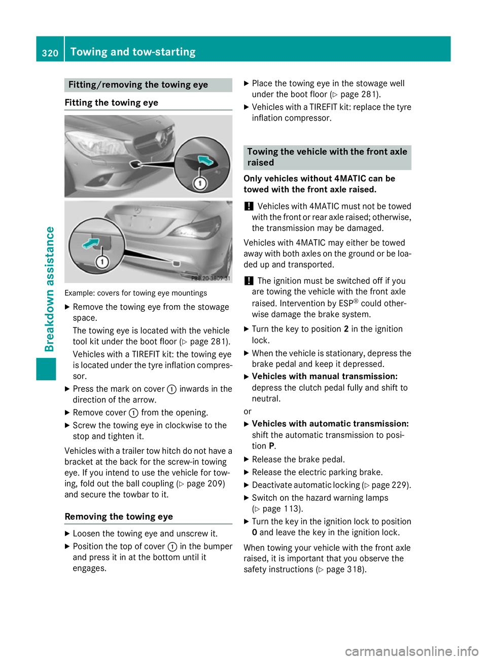
Fitting the towing eye Example: covers for towing eye mountings
X Remove the towing eye from the stowage
space.
The towing eye is located with the vehicle
tool kit under the boot floor (Y page 281).
Vehicles with a TIREFIT kit: the towing eye
is located under the tyre inflation compres-
sor.
X Press the mark on cover :inwards in the
direction of the arrow.
X Remove cover :from the opening.
X Screw the towing eye in clockwise to the
stop and tighten it.
Vehicles with a trailer tow hitch do not have a bracket at the back for the screw-in towing
eye. If you intend to use the vehicle for tow-
ing, fold out the ball coupling (Y page 209)
and secure the towbar to it.
Removing the towing eye X
Loosen the towing eye and unscrew it.
X Position the top of cover :in the bumper
and press it in at the bottom until it
engages. X
Place the towing eye in the stowage well
under the boot floor (Y page 281).
X Vehicles with a TIREFIT kit: replace the tyre
inflation compressor. Towing the vehicle with the front axle
raised
Only vehicles without 4MATIC can be
towed with the front axle raised.
! Vehicles with 4MATIC must not be towed
with the front or rear axle raised; otherwise, the transmission may be damaged.
Vehicles with 4MATIC may either be towed
away with both axles on the ground or be loa-
ded up and transported.
! The ignition must be switched off if you
are towing the vehicle with the front axle
raised. Intervention by ESP ®
could other-
wise damage the brake system.
X Turn the key to position 2in the ignition
lock.
X When the vehicle is stationary, depress the
brake pedal and keep it depressed.
X Vehicles with manual transmission:
depress the clutch pedal fully and shift to
neutral.
or
X Vehicles with automatic transmission:
shift the automatic transmission to posi-
tion P.
X Release the brake pedal.
X Release the electric parking brake.
X Deactivate automatic locking (Y page 229).
X Switch on the hazard warning lamps
(Y page 113).
X Turn the key in the ignition lock to position
0 and leave the key in the ignition lock.
When towing your vehicle with the front axle
raised, it is important that you observe the
safety instructions (Y page 318).320
Towing and tow-startingBreakdown assistance
Page 353 of 373
limitation specified on the emergency spare
wheel.
Replace the tyres after six years at the latest,
regardless of wear. This also applies to the
emergency spare wheel. Removing the emergency spare wheel
Vehicles with the "Minispare" emergency spare
wheel:
The "Minispare" emergency spare wheel is
secured in emergency spare wheel bag :in
the boot.
X Open the boot lid.
X Release securing straps ;on emergency
spare wheel bag :.
X Remove emergency spare wheel bag :
with the "Minispare" emergency spare
wheel.
X Open emergency spare wheel bag :and
remove the "Minispare" emergency spare
wheel.
Observe the instructions and safety notes in
the "Fitting a wheel" section (Y page 336).Technical data
"Minispare" emer-
gency spare wheel
Tyres Steel wheel
T 125/80 R17 99 M
Tyre pressure: 420 kPa
(4.2 bar/61 psi) 3.5 B x 17 H2
ET 19.5350
Emergency spare wheelWheels and tyres
Page 356 of 373
sion surrounding the possible health risk
posed by electromagnetic fields.
Observe the notes on operating mobile
phones (Y page 286).
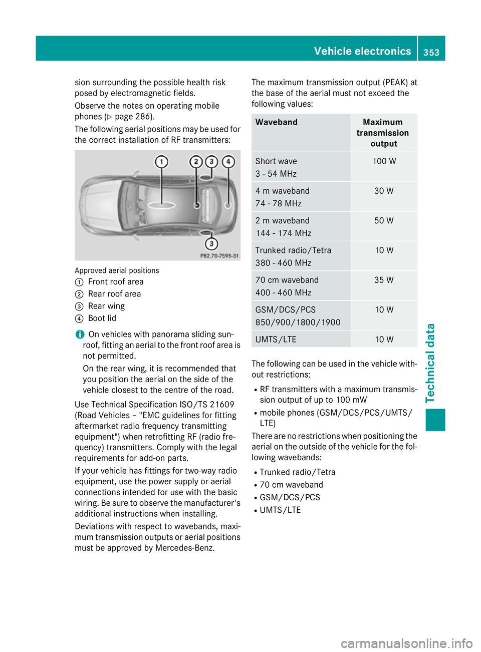
The following aerial positions may be used for the correct installation of RF transmitters: Approved aerial positions
:
Front roof area
; Rear roof area
= Rear wing
? Boot lid
i On vehicles with panorama sliding sun-
roof, fitting an aerial to the front roof area is not permitted.
On the rear wing, it is recommended that
you position the aerial on the side of the
vehicle closest to the centre of the road.
Use Technical Specification ISO/TS 21609
(Road Vehicles – "EMC guidelines for fitting
aftermarket radio frequency transmitting
equipment") when retrofitting RF (radio fre-
quency) transmitters. Comply with the legal
requirements for add-on parts.
If your vehicle has fittings for two-way radio
equipment, use the power supply or aerial
connections intended for use with the basic
wiring. Be sure to observe the manufacturer's additional instructions when installing.
Deviations with respect to wavebands, maxi-
mum transmission outputs or aerial positions must be approved by Mercedes-Benz. The maximum transmission output (PEAK) at
the base of the aerial must not exceed the
following values: Waveband Maximum
transmission output Short wave
3 - 54 MHz 100 W
4 m waveband
74 - 78 MHz 30 W
2 m waveband
144 - 174 MHz 50 W
Trunked radio/Tetra
380 - 460 MHz 10 W
70 cm waveband
400 - 460 MHz 35 W
GSM/DCS/PCS
850/900/1800/1900 10 W
UMTS/LTE 10 W
The following can be used in the vehicle with-
out restrictions:
R RF transmitters with a maximum transmis-
sion output of up to 100 mW
R mobile phones (GSM/DCS/PCS/UMTS/
LTE)
There are no restrictions when positioning the aerial on the outside of the vehicle for the fol-
lowing wavebands:
R Trunked radio/Tetra
R 70 cm waveband
R GSM/DCS/PCS
R UMTS/LTE Vehicle electronics
353Technical data Z
Page 365 of 373
i
Add washer fluid concentrate, e.g. MB
SummerFit or MB WinterFit, to the washer
fluid all year round. Vehicle data
General notes
Please note that for the specified vehicle
data: R the heights specified may vary as a result
of:
- tyres
- load
- condition of the suspension
- optional equipment
R optional equipment reduces the maximum
payload.
R vehicle-specific weight information can be
found on the vehicle identification plate
(Y page 354).
R only for certain countries: you can find vehi-
cle-specific vehicle data in the COC docu-
ments (CERTIFICATE OF CONFORMITY).
These documents are delivered with your
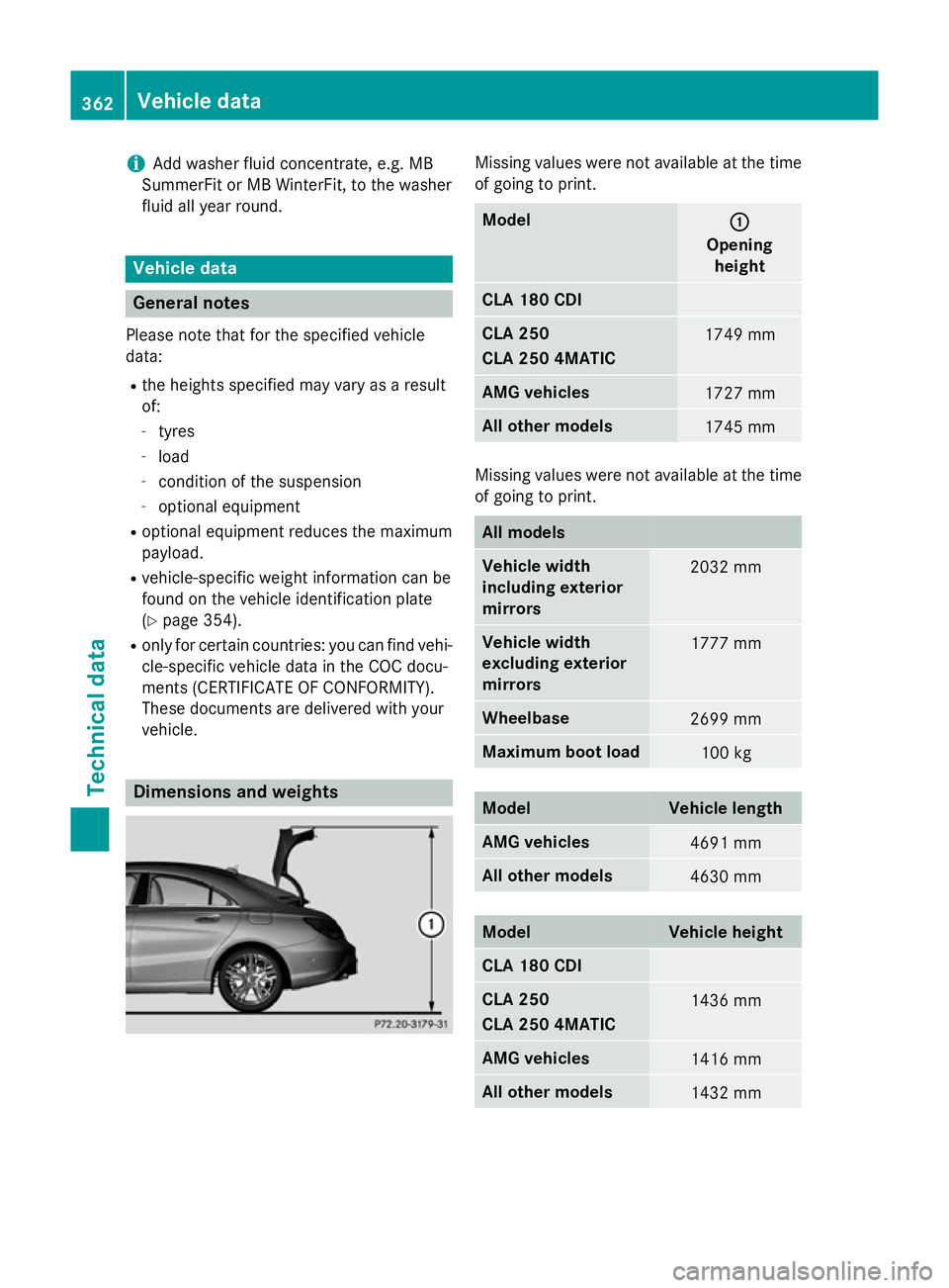
vehicle. Dimensions and weights Missing values were not available at the time
of going to print. Model
: :
Opening height CLA 180 CDI
CLA 250
CLA 250 4MATIC
1749 mm
AMG vehicles
1727 mm
All other models
1745 mm
Missing values were not available at the time
of going to print. All models
Vehicle width
including exterior
mirrors
2032 mm
Vehicle width
excluding exterior
mirrors
1777 mm
Wheelbase
2699 mm
Maximum boot load
100 kg
Model Vehicle length
AMG vehicles
4691 mm
All other models
4630 mm
Model Vehicle height
CLA 180 CDI
CLA 250
CLA 250 4MATIC
1436 mm
AMG vehicles
1416 mm
All other models
1432 mm362
Vehicle dataTechnical data