2013 MERCEDES-BENZ CLA COUPE phone
[x] Cancel search: phonePage 288 of 373
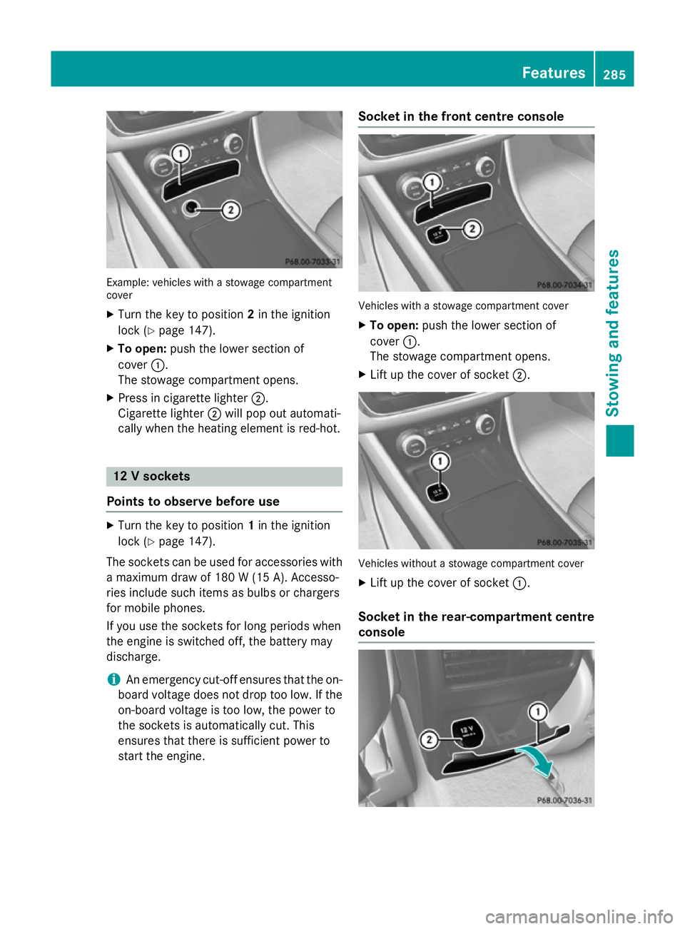
Example: vehicles with a stowage compartment
cover
X Turn the key to position 2in the ignition
lock (Y page 147).
X To open: push the lower section of
cover :.
The stowage compartment opens.
X Press in cigarette lighter ;.
Cigarette lighter ;will pop out automati-
cally when the heating element is red-hot. 12 V sockets
Points to observe before use X
Turn the key to position 1in the ignition
lock (Y page 147).
The sockets can be used for accessories with a maximum draw of 180 W (15 A). Accesso-
ries include such items as bulbs or chargers
for mobile phones.
If you use the sockets for long periods when
the engine is switched off, the battery may
discharge.
i An emergency cut-off ensures that the on-
board voltage does not drop too low. If the on-board voltage is too low, the power to
the sockets is automatically cut. This
ensures that there is sufficient power to
start the engine. Socket in the front centre console
Vehicles with a stowage compartment cover
X To open: push the lower section of
cover :.
The stowage compartment opens.
X Lift up the cover of socket ;. Vehicles without a stowage compartment cover
X Lift up the cover of socket :.
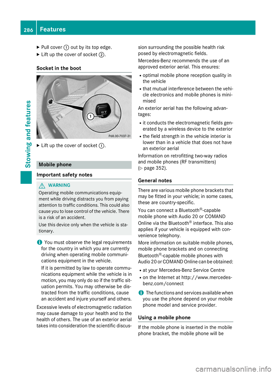
Socket in the rear-compartment centre
console Features
285Stowing and features Z
Page 289 of 373
X
Pull cover :out by its top edge.
X Lift up the cover of socket ;.
Socket in the boot X
Lift up the cover of socket :.Mobile phone
Important safety notes G
WARNING
Operating mobile communications equip-
ment while driving distracts you from paying
attention to traffic conditions. This could also cause you to lose control of the vehicle. There
is a risk of an accident.
Use this device only when the vehicle is sta-
tionary.
i You must observe the legal requirements
for the country in which you are currently
driving when operating mobile communi-
cations equipment in the vehicle.
If it is permitted by law to operate commu-
nications equipment while the vehicle is in
motion, you may only do so if the traffic sit-
uation permits. You may otherwise be dis-
tracted from the traffic conditions, cause
an accident and injure yourself and others.
Excessive levels of electromagnetic radiation
may cause damage to your health and to the
health of others. The use of an exterior aerial takes into consideration the scientific discus- sion surrounding the possible health risk
posed by electromagnetic fields.
Mercedes-Benz recommends the use of an
approved exterior aerial. This ensures:
R optimal mobile phone reception quality in
the vehicle
R that mutual interference between the vehi-
cle electronics and mobile phones is mini-
mised
An exterior aerial has the following advan-
tages:
R it conducts the electromagnetic fields gen-
erated by a wireless device to the exterior
R the field strength in the vehicle interior is
lower than in a vehicle that does not have
an exterior aerial
Information on retrofitting two-way radios
and mobile phones (RF transmitters)
(Y page 352).
General notes There are various mobile phone brackets that
may be fitted in your vehicle; in some cases,
these are country-specific.
You can connect a Bluetooth ®
-capable
mobile phone with Audio 20 or COMAND
Online via the Bluetooth ®
interface. This also
applies if your vehicle is equipped with con-
venience telephony.
More information on suitable mobile phones,
mobile phone brackets and on connecting
Bluetooth ®
-capable mobile phones with
Audio 20 or COMAND Online can be obtained:
R at your Mercedes-Benz Service Centre
R on the Internet at http://www.mercedes-
benz.com/connect
i The functions and services available when
you use the phone depend on your mobile
phone model and service provider.
Using a mobile phone If the mobile phone is inserted in the mobile
phone bracket, the mobile phone will be286
FeaturesStowing and features
Page 290 of 373
charged and connected with the exterior aer-
ial.
X Open the telephone compartment
(Y page 278).
X Place the mobile phone bracket into the
pre-installed fitting; see the separate instal- lation instructions for the mobile phone fit-
ting.
X Insert the mobile phone into the mobile
phone bracket; see the separate installa-
tion instructions for the mobile phone fit-
ting.
Operating the mobile phone You can operate the telephone using the
6 and~ buttons on the multifunction
steering wheel. You can operate other mobile
phone functions via the on-board computer
(Y page 221).
When you remove the key from the ignition
lock, the mobile phone is disconnected from
the hands-free system. Active calls will first
be transferred to the mobile phone directly.
Mobile phone bracket in the stowage
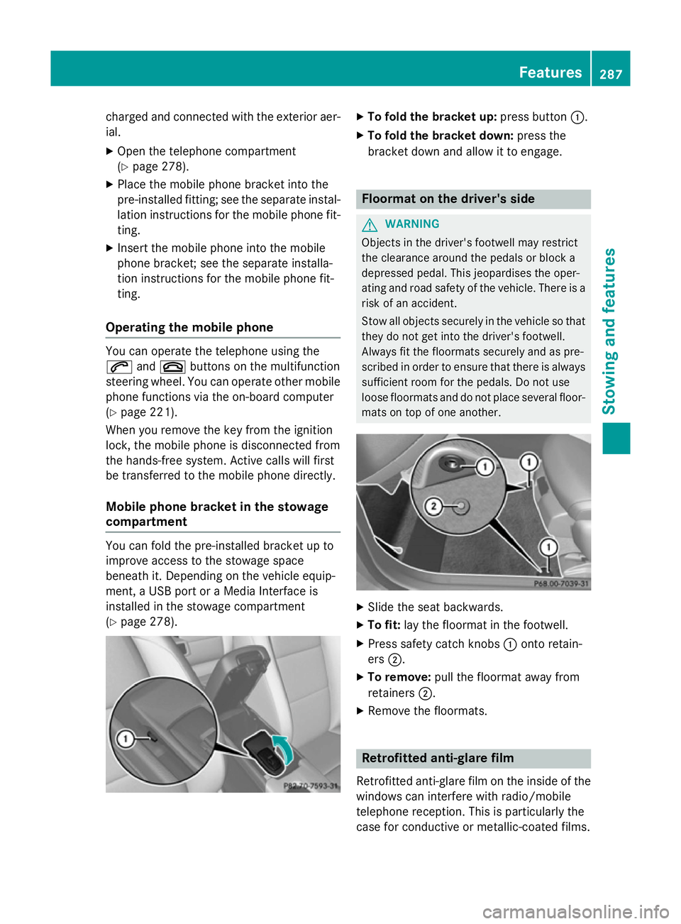
compartment You can fold the pre-installed bracket up to
improve access to the stowage space
beneath it. Depending on the vehicle equip-
ment, a USB port or a Media Interface is
installed in the stowage compartment
(Y
page 278). X
To fold the bracket up: press button:.
X To fold the bracket down: press the
bracket down and allow it to engage. Floormat on the driver's side
G
WARNING
Objects in the driver's footwell may restrict
the clearance around the pedals or block a
depressed pedal. This jeopardises the oper-
ating and road safety of the vehicle. There is a risk of an accident.
Stow all objects securely in the vehicle so that
they do not get into the driver's footwell.
Always fit the floormats securely and as pre-
scribed in order to ensure that there is always sufficient room for the pedals. Do not use
loose floormats and do not place several floor-mats on top of one another. X
Slide the seat backwards.
X To fit: lay the floormat in the footwell.
X Press safety catch knobs :onto retain-
ers ;.
X To remove: pull the floormat away from
retainers ;.
X Remove the floormats. Retrofitted anti-glare film
Retrofitted anti-glare film on the inside of the
windows can interfere with radio/mobile
telephone reception. This is particularly the
case for conductive or metallic-coated films. Features
287Stowing and features Z
Page 297 of 373
Damage to the engine or exhaust system is
caused by the following:
R using engine oils and oil filters that have
not been specifically approved for the
service system
R changing the engine oil and oil filter after
missing the change interval required by
the service system
R using engine oil additives
! Do not add too much oil. Topping up with
too much engine oil can result in damage to
the engine or to the catalytic converter.
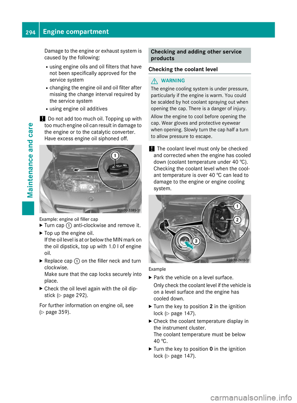
Have excess engine oil siphoned off. Example: engine oil filler cap
X Turn cap :anti-clockwise and remove it.
X Top up the engine oil.
If the oil level is at or below the MIN mark on
the oil dipstick, top up with 1.0 lof engine
oil.
X Replace cap :on the filler neck and turn
clockwise.
Make sure that the cap locks securely into place.
X Check the oil level again with the oil dip-
stick (Y page 292).
For further information on engine oil, see
(Y page 359). Checking and adding other service
products
Checking the coolant level G
WARNING
The engine cooling system is under pressure, particularly if the engine is warm. You could
be scalded by hot coolant spraying out when
opening the cap. There is a danger of injury.
Allow the engine to cool before opening the
cap. Wear gloves and protective eyewear
when opening. Slowly turn the cap half a turn
to allow pressure to escape.
! The coolant level must only be checked
and corrected when the engine has cooled
down (coolant temperature under 40 †).
Checking the coolant level when the cool-
ant temperature is over 40 † can lead to
damage to the engine or engine cooling
system. Example
X Park the vehicle on a level surface.
Only check the coolant level if the vehicle is
on a level surface and the engine has
cooled down.
X Turn the key to position 2in the ignition
lock (Y page 147).
X Check the coolant temperature display in
the instrument cluster.
The coolant temperature must be below
40 †.
X Turn the key to position 0in the ignition
lock (Y page 147). 294
Engine compartmentMaintenance and care
Page 315 of 373
i
In your vehicle, you will find a sticker with
the Mercedes-Benz Service24h telephone
number, e.g. on the B-pillar on the driver's
side.
X Correct the tyre pressure if it is still at least
130 kPa (1.3 bar/19 psi). See the fuel filler
flap for values.
X To increase the tyre pressure: switch on
the tyre inflation compressor. X
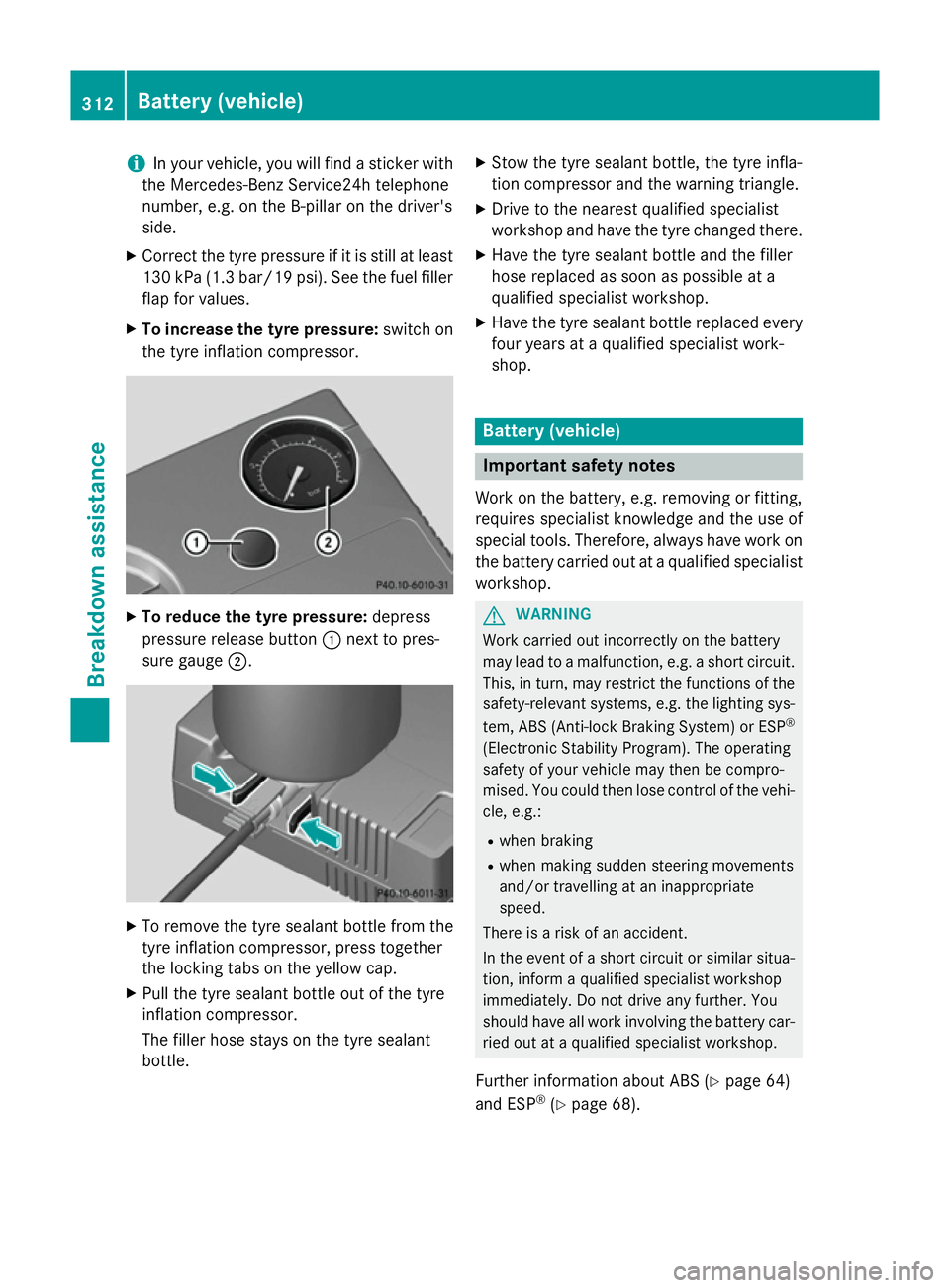
To reduce the tyre pressure: depress
pressure release button :next to pres-
sure gauge ;. X
To remove the tyre sealant bottle from the
tyre inflation compressor, press together
the locking tabs on the yellow cap.
X Pull the tyre sealant bottle out of the tyre
inflation compressor.
The filler hose stays on the tyre sealant
bottle. X
Stow the tyre sealant bottle, the tyre infla-
tion compressor and the warning triangle.
X Drive to the nearest qualified specialist
workshop and have the tyre changed there.
X Have the tyre sealant bottle and the filler
hose replaced as soon as possible at a
qualified specialist workshop.
X Have the tyre sealant bottle replaced every
four years at a qualified specialist work-
shop. Battery (vehicle)
Important safety notes
Work on the battery, e.g. removing or fitting,
requires specialist knowledge and the use of
special tools. Therefore, always have work on the battery carried out at a qualified specialist
workshop. G
WARNING
Work carried out incorrectly on the battery
may lead to a malfunction, e.g. a short circuit. This, in turn, may restrict the functions of the
safety-relevant systems, e.g. the lighting sys-
tem, ABS (Anti-lock Braking System) or ESP ®
(Electronic Stability Program). The operating
safety of your vehicle may then be compro-
mised. You could then lose control of the vehi-
cle, e.g.:
R when braking
R when making sudden steering movements
and/or travelling at an inappropriate
speed.
There is a risk of an accident.
In the event of a short circuit or similar situa-
tion, inform a qualified specialist workshop
immediately. Do not drive any further. You
should have all work involving the battery car- ried out at a qualified specialist workshop.
Further information about ABS (Y page 64)
and ESP ®
(Y page 68). 312
Battery (vehicle)Breakdown assistance
Page 336 of 373
first be taught-in to the tyre pressure monitor.
If there is a substantial loss of pressure, the
warning threshold for the warning message is aligned to the reference values taught-in.
Restart the tyre pressure monitor after
adjusting to the cold tyre pressure
(Y page 334). The current pressures are
saved as new reference values. This will
ensure that a warning message will only
appear if the tyre pressure drops significantly.
The tyre pressure monitor does not warn you
of an incorrectly set tyre pressure. Observe
the notes on the recommended tyre pressure
(Y page 330).
The tyre pressure monitor is not able to warn
you of a sudden loss of pressure, e.g. if the
tyre is penetrated by a foreign object. In the
event of a sudden loss of pressure, bring the
vehicle to a halt by braking carefully. Avoid
abrupt steering manoeuvres.
The tyre pressure monitor has a yellow warn-
ing lamp in the instrument cluster for indicat- ing a pressure loss or malfunction. Depending
on how the warning lamp flashes or lights up, a tyre pressure that is too low or a malfunc-
tion in the tyre pressure monitor is indicated:
R if the warning lamp is lit continuously, the
tyre pressure on one or more tyres is sig-
nificantly too low. The tyre pressure moni-
tor is not malfunctioning.
R if the warning lamp flashes for around a
minute and then remains lit constantly, the tyre pressure monitor is malfunctioning.
i In addition to the warning lamp, a mes-
sage appears in the multifunction display.
Further information can be found on
(Y page 256).
If the tyre pressure monitor is malfunctioning,
it may take more than ten minutes for the tyre pressure warning lamp to inform you of the
malfunction by flashing for approximately one
minute and then remaining lit. Once the fault
has been rectified, the tyre pressure warning
lamp goes out after you have driven for a few
minutes. The tyre pressure values indicated by the on-
board computer may differ from those meas-
ured at a filling station using a pressure
gauge. The tyre pressures shown by the on-
board computer refer to those measured at
sea level. At high altitudes, the tyre pressure
values indicated by a pressure gauge are
higher than those shown by the on-board
computer. In this case, do not reduce the tyre
pressures.
The operation of the tyre pressure monitor
can be affected by interference from radio
transmitting equipment (e.g. radio head-
phones, two-way radios) that may be being
operated in or near the vehicle.
Checking the tyre pressure electroni-
cally X
Make sure that the key is in position 2in the
ignition lock (Y page 147).
X Press the =or; button on the steer-
ing wheel to select the Serv. Serv.menu.
X Press the 9or: button to select
Tyre pressure
Tyre pressure.
X Press the abutton.
The current tyre pressure for each wheel
will be shown in the multifunction display.
If the vehicle was parked for longer than
20 minutes, the Tyre Tyrepressures
pressures will
willbe
be
displayed after a few minutes of
displayed after a few minutes of
driving driving message is shown.
After a teach-in period, the tyre pressure
monitor automatically recognises new
wheels or new sensors. As long as a clear
allocation of the tyre pressure values to the
individual wheels is not possible, the Tyre Tyre
pressure monitor active
pressure monitor active message is
shown instead of the tyre pressure display.
The tyre pressures are already being moni-
tored.
i If an emergency spare wheel is fitted, the
system may continue to show the tyre pres-
sure of the wheel that has been removed
for a few minutes. If this occurs, note that
the value displayed for the position where Tyre pressure
333Wheels and tyres Z
Page 355 of 373
Useful information
i This Owner's Manual describes all mod-
els, series and optional equipment for your
vehicle that were available at the time of
going to press. National variations are pos- sible. Note that your vehicle may not be
equipped with all of the functions descri-
bed. This is also the case for systems and
functions relevant to safety.
i Read the information on qualified special-
ist workshops: (Y page 24). Information on technical data
General notes
You can find current technical data on the
Internet on our Mercedes‑ Benz homepage.
i The technical data was determined in
accordance with EU Directives. All data
applies to the vehicle's standard equip-
ment. The data may therefore differ for
vehicles with optional equipment. You can
obtain further information from a
Mercedes-Benz Service Centre. Vehicle electronics
Tampering with the engine electron-
ics
! Only have work carried out on the engine
electronics and its associated parts, such
as control units, sensors, actuating com-
ponents and connector leads, at a qualified specialist workshop. Vehicle components
may otherwise wear more quickly and the
vehicle's operating permit may be invalida-
ted. Retrofitting two-way radios and
mobile phones (RF transmitters)
G
WARNING
If RF transmitters are tampered with or not
properly retrofitted, the electromagnetic radi- ation they emit can interfere with the vehicle
electronics. This may jeopardise the opera-
tional safety of the vehicle. There is a risk of an
accident.
You should have all work on electrical and
electronic components carried out at a quali-
fied specialist workshop. G
WARNING
If you use the RF transmitter in the vehicle in
an improper way, its electromagnetic radia-
tion can disrupt vehicle electronics, e.g. if:
R the RF transmitter is not connected to an
exterior aerial
R the exterior aerial is fitted incorrectly or is
not a low-reflection aerial
This can jeopardise the operating safety of the vehicle. There is a risk of an accident.
Have the low-reflection exterior aerial fitted at
a qualified specialist workshop. When oper-
ating in the vehicle, always connect the RF
transmitter to the low-reflection exterior aer-
ial.
! The operating permit may be invalidated if
the instructions for installation and use of
RF transmitters are not observed.
In particular, the following conditions must be complied with:
R only approved wavebands may be used.
R observe the maximum permissible out-
put in these wavebands.
R only approved aerial positions may be
used.
Excessive levels of electromagnetic radiation
may cause damage to your health and to the
health of others. The use of an exterior aerial
takes into consideration the scientific discus- 352
Vehicle electronicsTechnical data
Page 356 of 373
sion surrounding the possible health risk
posed by electromagnetic fields.
Observe the notes on operating mobile
phones (Y page 286).
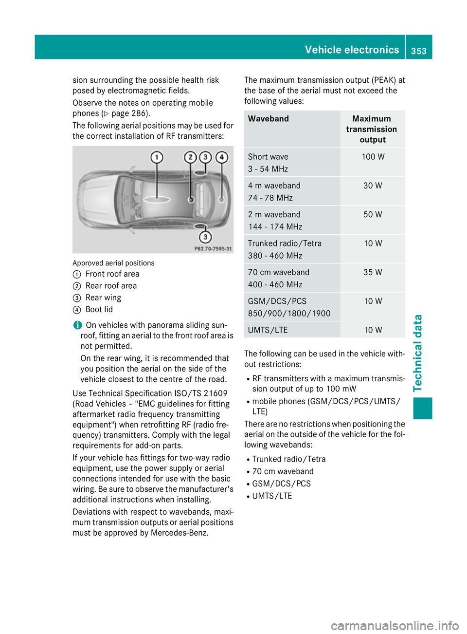
The following aerial positions may be used for the correct installation of RF transmitters: Approved aerial positions
:
Front roof area
; Rear roof area
= Rear wing
? Boot lid
i On vehicles with panorama sliding sun-
roof, fitting an aerial to the front roof area is not permitted.
On the rear wing, it is recommended that
you position the aerial on the side of the
vehicle closest to the centre of the road.
Use Technical Specification ISO/TS 21609
(Road Vehicles – "EMC guidelines for fitting
aftermarket radio frequency transmitting
equipment") when retrofitting RF (radio fre-
quency) transmitters. Comply with the legal
requirements for add-on parts.
If your vehicle has fittings for two-way radio
equipment, use the power supply or aerial
connections intended for use with the basic
wiring. Be sure to observe the manufacturer's additional instructions when installing.
Deviations with respect to wavebands, maxi-
mum transmission outputs or aerial positions must be approved by Mercedes-Benz. The maximum transmission output (PEAK) at
the base of the aerial must not exceed the
following values: Waveband Maximum
transmission output Short wave
3 - 54 MHz 100 W
4 m waveband
74 - 78 MHz 30 W
2 m waveband
144 - 174 MHz 50 W
Trunked radio/Tetra
380 - 460 MHz 10 W
70 cm waveband
400 - 460 MHz 35 W
GSM/DCS/PCS
850/900/1800/1900 10 W
UMTS/LTE 10 W
The following can be used in the vehicle with-
out restrictions:
R RF transmitters with a maximum transmis-
sion output of up to 100 mW
R mobile phones (GSM/DCS/PCS/UMTS/
LTE)
There are no restrictions when positioning the aerial on the outside of the vehicle for the fol-
lowing wavebands:
R Trunked radio/Tetra
R 70 cm waveband
R GSM/DCS/PCS
R UMTS/LTE Vehicle electronics
353Technical data Z