2013 MERCEDES-BENZ CLA COUPE lock
[x] Cancel search: lockPage 190 of 373
R
you depress the brake pedal again with a
certain amount of pressure until :disap-
pears from the multifunction display.
R you secure the vehicle using the electric
parking brake.
R you activate DISTRONIC PLUS.
i After a short period, the vehicle is secured
by the electric parking brake, thus relieving
the service brake.
The electric parking brake secures the vehicle
automatically if the HOLD function is activa-
ted and:
R the driver's door is open and the driver's
seat belt is unfastened
R the engine is switched off, unless it is auto-
matically switched off by the ECO start/
stop function
R a system fault occurs
R the power supply is not sufficient
Vehicles with automatic transmission
If a malfunction occurs, then the transmission may also be shifted into position Pautomat-
ically.
Vehicles with manual transmission
The Brake immediately Brake immediately message can also
appear in the multifunction display.
X Immediately depress the brake pedal firmly
until the warning message in the multifunc-
tion display goes out.
The HOLD function is deactivated.
A horn will sound at regular intervals if you
turn off the engine, take off your seat belt or
open the driver's door when the HOLD func-
tion is activated. The horn alerts you to the
fact that the HOLD function is still activated.
If you attempt to lock the vehicle, the tone
becomes louder. The vehicle cannot be
locked until you have deactivated the HOLD
function.
i Once you have switched off the engine,
you cannot restart it until you have deacti-
vated the HOLD function. RACE START
Important safety notes RACE START enables optimum acceleration
from a standing start. The precondition for
this is a suitable high-grip road surface.
Only activate RACE START on dedicated race
circuits.
i RACE START is only available in AMG vehi-
cles.
Activation conditions You can activate RACE START if:
R the doors, the bonnet and the boot lid are
closed
R the engine is running and the transmission,
traction control and engine are at operating temperature
R SPORT handling mode is activated
(Y page 70)
R the steering wheel is in the straight-ahead
position.
R the vehicle is stationary and the brake
pedal is depressed (left foot)
R the transmission is in position D
R drive program Mis selected (Y page 159).
Activating RACE START X
Depress the brake pedal with your left foot
and keep it depressed.
X Pull and hold both steering wheel gearshift
paddles.
X The RACE START Confirm: Paddle UP RACE START Confirm: Paddle UP
Cancel: Paddle DOWN
Cancel: Paddle DOWN message appears
in the multifunction display.
X Release both steering wheel gearshift pad-
dles.
i If the activation conditions are no longer
fulfilled, RACE START is cancelled. The
RACE START not possible See Own‐ RACE START not possible See Own‐
er's er's Manual
Manual message appears in the mul-
tifunction display. Driving syste
ms
187Driving an d parking Z
Page 194 of 373
Deactivating/activating PARKTRONIC
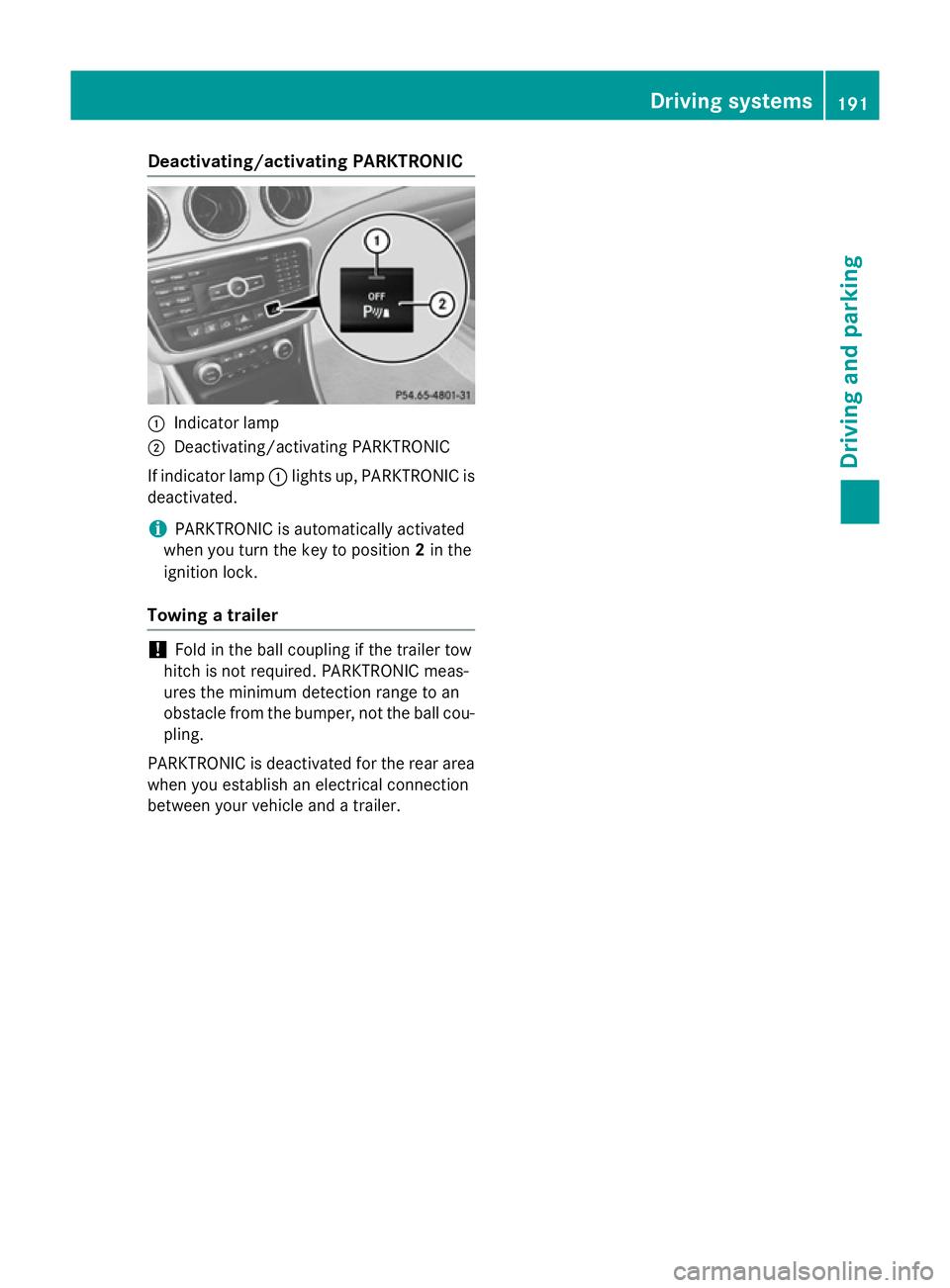
:
Indicator lamp
; Deactivating/activating PARKTRONIC
If indicator lamp :lights up, PARKTRONIC is
deactivated.
i PARKTRONIC is automatically activated
when you turn the key to position 2in the
ignition lock.
Towing a trailer !
Fold in the ball coupling if the trailer tow
hitch is not required. PARKTRONIC meas-
ures the minimum detection range to an
obstacle from the bumper, not the ball cou-
pling.
PARKTRONIC is deactivated for the rear area when you establish an electrical connection
between your vehicle and a trailer. Driving syste
ms
191Driving an d parking Z
Page 196 of 373
Parking tips:
R on narrow roads, drive as closely as possi-
ble past the parking space.
R parking spaces that are littered or over-
grown might be identified or measured
incorrectly.
R parking spaces that are partially occupied
by trailer drawbars might not be identified
as such or be measured incorrectly.
R snowfall or heavy rain may lead to a parking
space being measured inaccurately.
R pay attention to the PARKTRONIC
(Y page 190) warning messages during the
parking procedure.
R you can intervene in the steering procedure
to correct it at any time. Active Parking
Assist will then be cancelled.
R when transporting a load which protrudes
from your vehicle, you should not use
Active Parking Assist.
R never use Active Parking Assist when snow
chains are fitted.
R make sure that the tyre pressures are
always correct. This has a direct influence
on the parking characteristics of the vehi-
cle.
Use Active Parking Assist for parking spaces
that are:
R parallel or at right angles to the direction of
travel
R on straight roads, not bends
R on the same level as the road, e.g. not on
the pavement
Detecting parking spaces Objects located above the height range of
Active Parking Assist will not be detected
when the parking space is measured. These
are not taken into account when the parking
procedure is calculated, e.g. overhanging
loads, tail sections or loading ramps of goods
vehicles. G
WARNING
If objects are located above the detection
range, Active Parking Assist may start to steer into the parking space too soon. As a result,
you could cause a collision. There is a risk of
an accident.
If objects are located above the detection
range, stop the vehicle and switch Active
Parking Assist off.
For further information on the detection
range (Y page 189).
Active Parking Assist does not support you
parking in spaces at right angles to the direc-
tion of travel if:
R two parking spaces are located directly
next to one another
R the parking space is directly next to a low
obstacle such as a low kerb stone
R you forward park
Active Parking Assist does not support you
parking in spaces that are parallel or at right
angles to the direction of travel if:
R the parking space is on a kerb stone
R the parking space appears to be blocked,
for example by foliage or grass paving
blocks
R the range of movement is too small
R the parking space is bordered by an obsta-
cle which is not clearly defined such as a
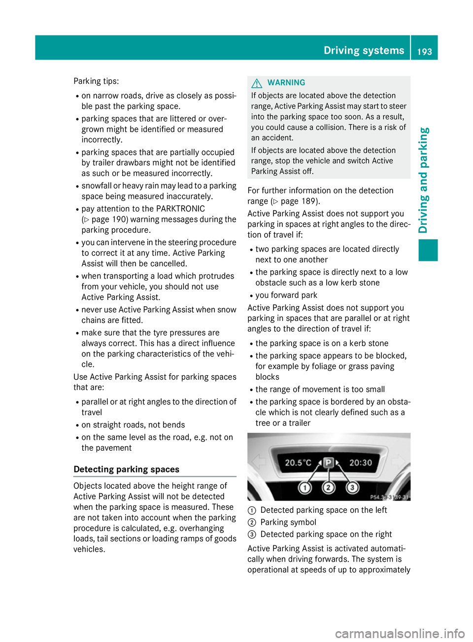
tree or a trailer :
Detected parking space on the left
; Parking symbol
= Detected parking space on the right
Active Parking Assist is activated automati-
cally when driving forwards. The system is
operational at speeds of up to approximately Driving systems
193Driving and parking Z
Page 201 of 373
Activating/deactivating the reversing
camera X
To activate: make sure that the key is in
position 2in the ignition lock.
X Make sure that the "Activation by R gear"
function is selected in the Audio system/
COMAND Online; see the separate operat-
ing instructions.
X Engage reverse gear.
Guide lines are used to show the area
behind the vehicle in the Audio/COMAND
display. Function mode display for vehicles with COMAND
Online and a trailer tow hitch
X To change the function mode in vehi-
cles with COMAND Online and trailer
tow hitch: using the COMAND controller,
select symbol :for the "Reverse parking"
function; see the separate COMAND Online
operating instructions.
or
X Select symbol ;for the "Coupling up a
trailer" function (see the separate
COMAND Online operating instructions).
The symbol of the selected function is high-
lighted.
To deactivate: the reversing camera deacti-
vates if you shift the transmission to Pon
vehicles with automatic transmission or after driving forwards a short distance. Displays in the Audio/COMAND display The reversing camera may show a distorted
view of obstacles or show them incorrectly or not at all. Obstacles are not shown by the
reversing camera in the following locations:
R very close to the rear bumper
R under the rear bumper
R in close range above the handle on the boot
lid
! Objects not at ground level may appear to
be further away than they actually are, e.g.:
R the bumper of a parked vehicle
R the drawbar of a trailer
R the ball coupling of a trailer tow hitch
R the rear section of an HGV
R a slanted post
Use the guidelines only for orientation.
Approach objects no further than the bot-
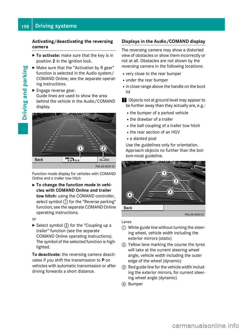
tom-most guideline. Lanes
:
White guide line without turning the steer-
ing wheel, vehicle width including the
exterior mirrors (static)
; Yellow lane marking the course the tyres
will take at the current steering wheel
angle, vehicle width including the outer
edge of the wheel (dynamic)
= Red guide line for the vehicle width includ-
ing the exterior mirrors, for current steer-
ing wheel angle (dynamic)
? Bumper 198
Driving systemsDriving and pa
rking
Page 208 of 373
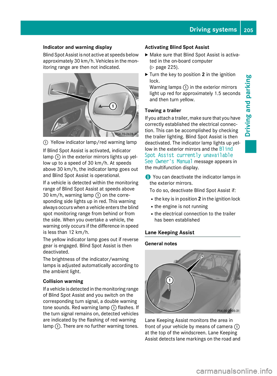
Indicator and warning display
Blind Spot Assist is not active at speeds below
approximately 30 km/h. Vehicles in the mon-itoring range are then not indicated. :
Yellow indicator lamp/red warning lamp
If Blind Spot Assist is activated, indicator
lamp :in the exterior mirrors lights up yel-
low up to a speed of 30 km/h. At speeds
above 30 km/h, the indicator lamp goes out
and Blind Spot Assist is operational.
If a vehicle is detected within the monitoring
range of Blind Spot Assist at speeds above
30 km/h, warning lamp :on the corre-
sponding side lights up in red. This warning
always occurs when a vehicle enters the blind
spot monitoring range from behind or from
the side. When you overtake a vehicle, the
warning only occurs if the difference in speed is less than 12 km/h.
The yellow indicator lamp goes out if reversegear is engaged. Blind Spot Assist is then
deactivated.
The brightness of the indicator/warning
lamps is adjusted automatically according to
the ambient light.
Collision warning
If a vehicle is detected in the monitoring range
of Blind Spot Assist and you switch on the
corresponding turn signal, a double warning
tone sounds. Red warning lamp :flashes. If
the turn signal remains on, detected vehicles
are indicated by the flashing of red warning
lamp :. There are no further warning tones. Activating Blind Spot Assist
X Make sure that Blind Spot Assist is activa-
ted in the on-board computer
(Y page 225).
X Turn the key to position 2in the ignition
lock.
Warning lamps :in the exterior mirrors
light up red for approximately 1.5 seconds
and then turn yellow.
Towing a trailer
If you attach a trailer, make sure that you have
correctly established the electrical connec-
tion. This can be accomplished by checking
the trailer lighting. Blind Spot Assist is then
deactivated. The indicator lamp lights up yel-
low in the exterior mirrors and the Blind
Blind
Spot Assist currently unavailable Spot Assist currently unavailable
See Owner's Manual See Owner's Manual message appears in
the multifunction display.
i You can deactivate the indicator lamps in
the exterior mirrors.
To do so, deactivate Blind Spot Assist if:
R the key is in position 2in the ignition lock
R the engine is not running
R the electrical connection to the trailer
has been established
Lane Keeping Assist General notes
Lane Keeping Assist monitors the area in
front of your vehicle by means of camera
:
at the top of the windscreen. Lane Keeping
Assist detects lane markings on the road and Driving systems
205Driving and parking Z
Page 213 of 373
X
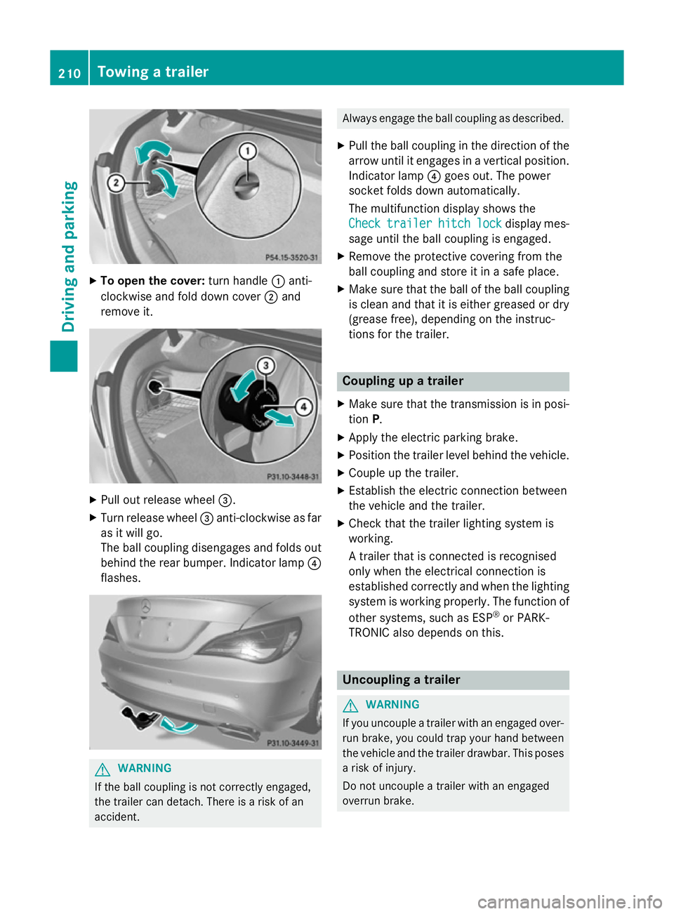
To open the cover: turn handle:anti-
clockwise and fold down cover ;and
remove it. X
Pull out release wheel =.
X Turn release wheel =anti-clockwise as far
as it will go.
The ball coupling disengages and folds out
behind the rear bumper. Indicator lamp ?
flashes. G
WARNING
If the ball coupling is not correctly engaged,
the trailer can detach. There is a risk of an
accident. Always engage the ball coupling as described.
X Pull the ball coupling in the direction of the
arrow until it engages in a vertical position.
Indicator lamp ?goes out. The power
socket folds down automatically.
The multifunction display shows the
Check Check trailer
trailer hitch
hitchlock
lockdisplay mes-
sage until the ball coupling is engaged.
X Remove the protective covering from the
ball coupling and store it in a safe place.
X Make sure that the ball of the ball coupling
is clean and that it is either greased or dry
(grease free), depending on the instruc-
tions for the trailer. Coupling up a trailer
X Make sure that the transmission is in posi-
tion P.
X Apply the electric parking brake.
X Position the trailer level behind the vehicle.
X Couple up the trailer.
X Establish the electric connection between
the vehicle and the trailer.
X Check that the trailer lighting system is
working.
A trailer that is connected is recognised
only when the electrical connection is
established correctly and when the lighting system is working properly. The function of
other systems, such as ESP ®
or PARK-
TRONIC also depends on this. Uncoupling a trailer
G
WARNING
If you uncouple a trailer with an engaged over- run brake, you could trap your hand between
the vehicle and the trailer drawbar. This poses a risk of injury.
Do not uncouple a trailer with an engaged
overrun brake. 210
Towing a trailerDriving an
d parking
Page 214 of 373
!
Do not disconnect a trailer with an
engaged overrun brake. Otherwise, your
vehicle could be damaged by the rebound- ing of the overrun brake.
! Remove the installed adapter cable
before folding in the ball coupling. Other-
wise, damage may occur to the rear
bumper and the adapter cable.
X Make sure that the transmission is in posi-
tion P.
X Apply the electric parking brake.
X Secure the trailer against rolling away.
X Remove the trailer cable and decouple the
trailer. Folding in the ball coupling
G
WARNING
If you release the ball coupling or it does not
engage correctly when folding in, it will swing out. Within pivoting range of the ball coupling,
there is an increased risk of an accident and
injury.
Only release the ball coupling if the pivoting
range is unobstructed. Always make sure that the ball coupling engages when folding in.
X Fold the ball coupling back in if you are not
using the trailer tow hitch.
X Place the protective covering on the ball
coupling.
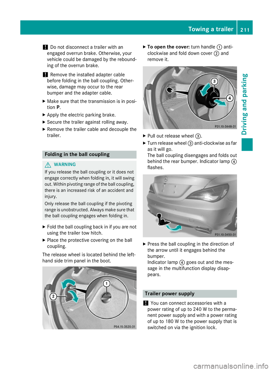
The release wheel is located behind the left-
hand side trim panel in the boot. X
To open the cover: turn handle:anti-
clockwise and fold down cover ;and
remove it. X
Pull out release wheel =.
X Turn release wheel =anti-clockwise as far
as it will go.
The ball coupling disengages and folds out
behind the rear bumper. Indicator lamp ?
flashes. X
Press the ball coupling in the direction of
the arrow until it engages behind the
bumper.
Indicator lamp ?goes out and the mes-
sage in the multifunction display disap-
pears. Trailer power supply
! You can connect accessories with a
power rating of up to 240 W to the perma-
nent power supply and with a power rating of up to 180 W to the power supply that is
switched on via the ignition lock. Towing a trailer
211Driving and parking Z
Page 215 of 373
The trailer battery may not be charged from
the power supply.
X To switch the connected power supply
on or off: turn the key in the ignition lock to
position 2or 0respectively.
When it leaves the factory, your vehicle's
trailer socket is equipped with a permanent
power supply and a power supply that is
switched on via the ignition lock.
The permanent power supply is supplied via
trailer socket pin 9.
The power supply that is switched on via the
ignition lock is supplied via trailer socket pin
10.
The trailer's permanent power supply is
switched off in the event of low vehicle supply
voltage and after six hours at the latest.
You can find more information about instal-
ling the trailer electrics at a qualified special- ist workshop. Bulb failure indicator for LED lamps
i If LED lamps are fitted in the trailer, an
error message may appear in the multi-
function display even if there is no fault. The
reason for the error message could be that the current has fallen below the minimum
of 50 mA.
To ensure reliable operation of the bulb failure
indicator, each LED chain in the trailer lighting must be guaranteed a minimum current of
50 mA. Trailer with 7-pin connector
General notes Trailer with 7-pin connector:
you can con-
nect to the 13-pin socket on the ball coupling
using an adapter or, if necessary, an adapter
cable. Both can be obtained at a qualified
specialist workshop. Fitting the adapter !
Make sure that there is sufficient cable
play so that the cable cannot become
detached when cornering.
! Remove the installed adapter cable
before folding in the ball coupling. Other-
wise, damage may occur to the rear
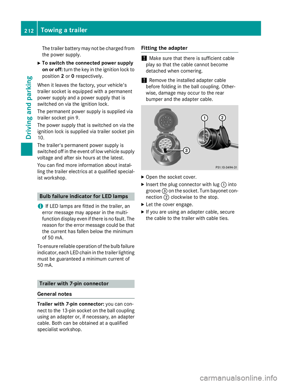
bumper and the adapter cable. X
Open the socket cover.
X Insert the plug connector with lug :into
groove =on the socket. Turn bayonet con-
nection ;clockwise to the stop.
X Let the cover engage.
X If you are using an adapter cable, secure
the cable to the trailer with cable ties. 212
Towing a trailerDriving and parking