Page 361 of 751
Maintenance
68
7
Type B
1. Remove the light assembly from the
vehicle by pushing the lens forward
and pulling the assembly out.
2. Disconnect the bulb electrical connec- tor.
3. Separate the socket and the lens parts by turning the socket counter clock-
wise until the tabs on the socket align
with the slots on the lens part.
4. Remove the bulb by pulling it straight out.
5. Insert a new bulb in the socket.
6. Reassemble the socket and the lens part.
7. Connect the bulb electrical connector.
8. Reinstall the light assembly to the body of the vehicle. Rear combination light bulb replacement (1) Stop and tail light
(2) Rear turn signal light
(3) Back-up light
(4) Tail light
(5) Rear fog light (if equipped)
1. Open the tailgate.2.Outside
Loosen the outside light assembly
retaining screws with a cross-tip screw-
driver.
OYN079051OYN079036
OYN079037
OYN079038
YN ENG 7.QXP 4/16/2012 10:10 AM Page 68
Page 376 of 751
Specifications & Consumer information
2
8
DIMENSIONS BULB WATTAGE
Item mm (in)
Overall length 4068 (160.16)
Overall width 1765 (69.49)
Overall height 1600 (62.99)
Front tread 1553 (61.14)* 1
/1547 (60.91)* 2
/1541 (60.67)* 3
Rear tread 1557 (61.30)* 1
/1551 (61.06)* 2
/1545 (60.83)* 3
Wheelbase 2615 (102.95)
* 1
Fitted with 195/65R15 tires.
* 2
Fitted with 205/55R16 tires.
* 3
Fitted with 205/50R17 tires.
Light BulbWattage
HeadlightsHigh55
Low55
Front turn signal lights21
Position lights5
Side repeater lights (if equipped)5
Front fog lights (if equipped) 27
Stop and tail lights21/5
Tail lights-
Rear turn signal lights 21
Back-up lights16
Rear fog lights (if equipped)21
High mounted stop light5
License plate lights5
Front map lamp10
Side room lamp (if equipped)5
Sunvisor lamp (if equipped)5
Luggage room lamp5
Glove box lamp5
YN eng 8.QXP 19.9.2011 19:05 Page 2
Page 401 of 751

Introduction
6
1
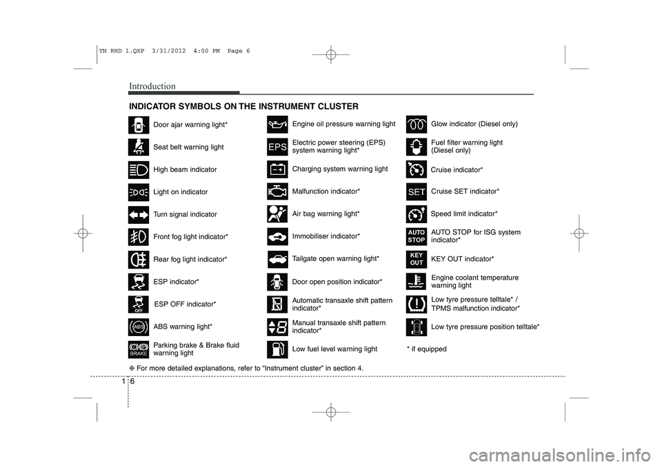
INDICATOR SYMBOLS ON THE INSTRUMENT CLUSTER
Engine coolant temperature
warning light
Seat belt warning light
High beam indicator
Turn signal indicator
ABS warning light*
Parking brake & Brake fluid
warning light
Malfunction indicator*
Immobiliser indicator*
Glow indicator (Diesel only)
Fuel filter warning light (Diesel only)
Tailgate open warning light*
❈ For more detailed explanations, refer to “Instrument cluster” in section 4.
Charging system warning light
Door ajar warning light*
ESP indicator*
ESP OFF indicator*
Front fog light indicator*
Engine oil pressure warning light
Electric power steering (EPS)
system warning light*
Air bag warning light*
Low tyre pressure telltale* / TPMS malfunction indicator*
Rear fog light indicator*
Cruise SET indicator*
Speed limit indicator* AUTO STOP for ISG system indicator*
Cruise indicator*
AUTOSTOP
KEY OUT indicator*KEY
OUT
Light on indicator
Automatic transaxle shift pattern indicator*
Manual transaxle shift pattern indicator*
* if equipped
Door open position indicator*
Low fuel level warning light Low tyre pressure position telltale*
YN RHD 1.QXP 3/31/2012 4:00 PM Page 6
Page 404 of 751

23
Your vehicle at a glance
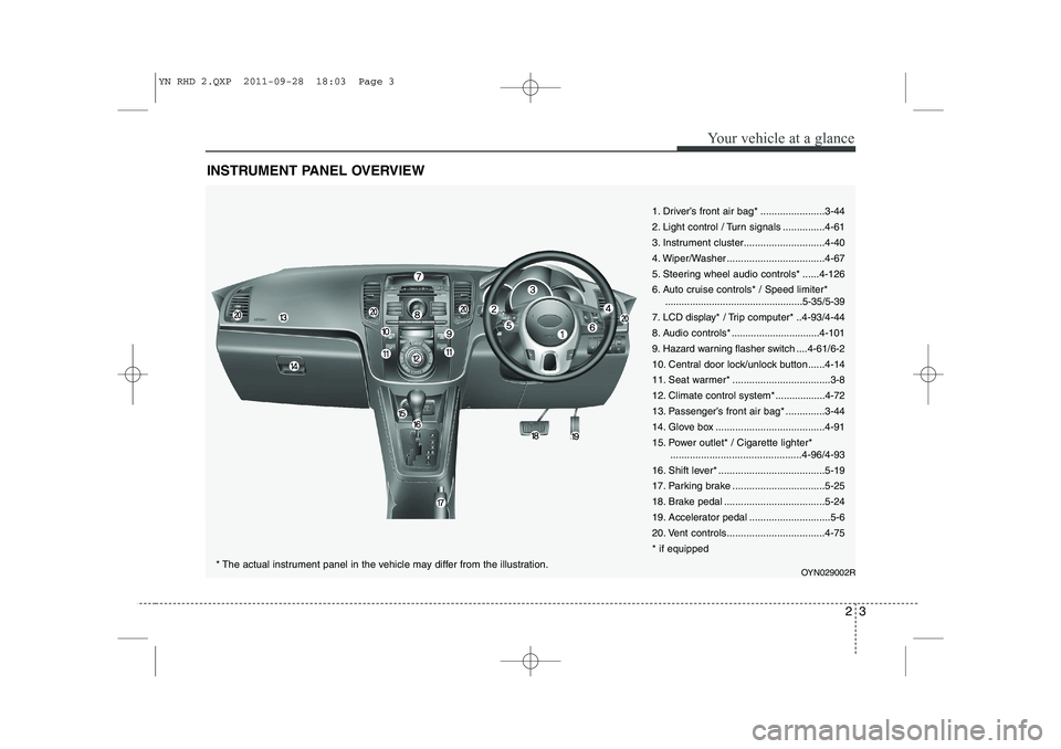
INSTRUMENT PANEL OVERVIEW
1. Driver’s front air bag* .......................3-44
2. Light control / Turn signals ...............4-61
3. Instrument cluster.............................4-40
4. Wiper/Washer ...................................4-67
5. Steering wheel audio controls* ......4-126
6. Auto cruise controls* / Speed limiter*..................................................5-35/5-39
7. LCD display* / Trip computer* ..4-93/4-44
8. Audio controls * ................................4-101
9. Hazard warning flasher switch ....4-61/6-2
10. Central door lock/unlock button......4-14
11. Seat warmer* ...................................3-8
12. Climate control system*..................4-72
13. Passenger’s front air bag* ..............3-44
14. Glove box .......................................4-91
15. Power outlet* / Cigarette lighter* ...............................................4-96/4-93
16. Shift lever* ......................................5-19
17. Parking brake .................................5-25
18. Brake pedal ....................................5-24
19. Accelerator pedal .............................5-6
20. Vent controls...................................4-75* if equipped
OYN029002R
* The actual instrument panel in the vehicle may differ from the illustration.
YN RHD 2.QXP 2011-09-28 18:03 Page 3
Page 443 of 751

Safety features of your vehicle
38
3
How does the air bag system operate
Air bags are activated (able to inflate if
necessary) only when the ignition
switch is turned to the ON or STARTposition.
Air bags inflate instantly in the event of serious frontal or side collision (ifequipped with side impact air bag or
curtain air bag) in order to help protect
the occupants from serious physical
injury.
There is no single speed at which the air bags will inflate.
Generally, air bags are designed to
inflate based upon the severity of a col-
lision and its direction. These two fac-
tors determine whether the sensors
produce an electronic deployment/inflation signal.
Air bag deployment depends on a number of factors including vehiclespeed, angles of impact and the densi-
ty and stiffness of the vehicles or
objects which your vehicle hits in the
collision. The determining, factors are
not limited to those mentioned above.
The front air bags will completely inflate and deflate in an instant. It is virtually impossible for you to see
the air bags inflate during an accident.
It is much more likely that you will sim-ply see the deflated air bags hanging
out of their storage compartments afterthe collision.
In order to help provide protection in a severe collision, the air bags must
inflate rapidly. The speed of air bag
inflation is a consequence of extremely
short time in which a collision occursand the need to get the air bag
between the occupant and the vehicle
structures before the occupant impacts
those structures. This speed of inflation
reduces the risk of serious or life-
threatening injuries in a severe collision
and is thus a necessary part of air bagdesign.
However, air bag inflation can also
cause injuries which can include facial
abrasions, bruises and broken bonesbecause the inflation speed also caus-
es the air bags to expand with a great
deal of force.
There are even circumstances under which contact with the steer-
ing wheel air bag can cause fatal
injuries, especially if the occupant
is positioned excessively close tothe steering wheel.
WARNING
To avoid severe personal injury or death caused by deploying air
bags in a collision, the driver
should sit as far back from the
steering wheel air bag as possible
(at least 250 mm (10 inches)
away). The front passenger should
always move their seat as far
back as possible and sit back intheir seat.
Air bag inflates instantly in an event of a collision, passengers
may be injured by the air bag
expansion force if they are not in
a proper position.
Air bag inflation may cause injuries including facial or bodily
abrasions, injuries from broken
glasses or burns.
YN RHD 3.QXP 3/31/2012 4:03 PM Page 38
Page 504 of 751
Features of your vehicle
40
4
INSTRUMENT CLUSTER
OYN049040/OYN049041* The actual cluster in the vehicle may differ from the illustration.
■
Petrol Engine
Type A
Type B
1. Tachometer
2. Turn signal indicators
3. Speedometer
4. Warning and indicator lights
5. Automatic transaxle shift position indicator* or Manual transaxle shift indicator*
6. Odometer/Tripmeter*
7. Fuel gauge* if equipped
YN RHD 4(~99).QXP 11/29/2012 11:01 AM Page 40
Page 505 of 751
441
Features of your vehicle
OYN049042/OYN049043* The actual cluster in the vehicle may differ from the illustration.
■
Diesel Engine
Type A
Type B
1. Tachometer
2. Turn signal indicators
3. Speedometer
4. Warning and indicator lights
5. Automatic transaxle shift position indicator* or Manual transaxle shift indicator*
6. Odometer/Tripmeter*
7. Fuel gauge* if equipped
YN RHD 4(~99).QXP 11/29/2012 11:02 AM Page 41
Page 513 of 751

449
Features of your vehicle
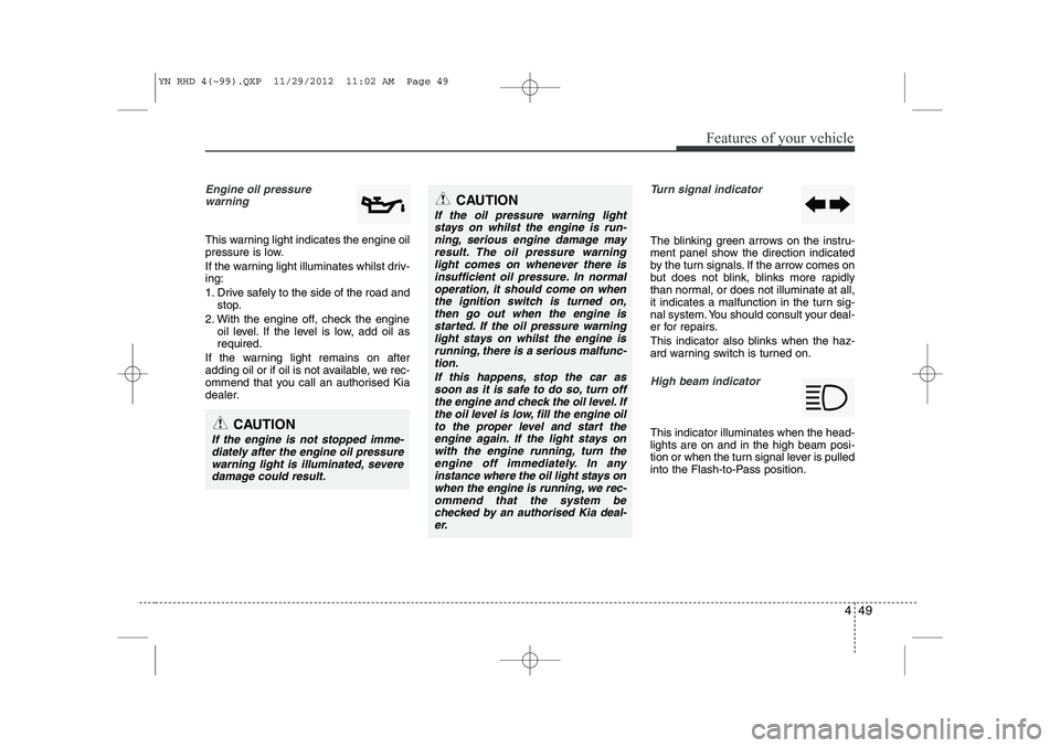
Engine oil pressure warning
This warning light indicates the engine oil
pressure is low.
If the warning light illuminates whilst driv- ing:
1. Drive safely to the side of the road and stop.
2. With the engine off, check the engine oil level. If the level is low, add oil as required.
If the warning light remains on after
adding oil or if oil is not available, we rec-
ommend that you call an authorised Kia
dealer.
Turn signal indicator
The blinking green arrows on the instru-
ment panel show the direction indicated
by the turn signals. If the arrow comes on
but does not blink, blinks more rapidly
than normal, or does not illuminate at all,
it indicates a malfunction in the turn sig-
nal system. You should consult your deal-
er for repairs.
This indicator also blinks when the haz-
ard warning switch is turned on.
High beam indicator
This indicator illuminates when the head- lights are on and in the high beam posi-
tion or when the turn signal lever is pulled
into the Flash-to-Pass position.CAUTION
If the engine is not stopped imme- diately after the engine oil pressure
warning light is illuminated, severedamage could result.
CAUTION
If the oil pressure warning lightstays on whilst the engine is run-
ning, serious engine damage mayresult. The oil pressure warninglight comes on whenever there is insufficient oil pressure. In normal
operation, it should come on whenthe ignition switch is turned on, then go out when the engine is
started. If the oil pressure warning light stays on whilst the engine isrunning, there is a serious malfunc-tion.
If this happens, stop the car assoon as it is safe to do so, turn offthe engine and check the oil level. If the oil level is low, fill the engine oil
to the proper level and start the engine again. If the light stays onwith the engine running, turn theengine off immediately. In any
instance where the oil light stays onwhen the engine is running, we rec-ommend that the system be checked by an authorised Kia deal-
er.
YN RHD 4(~99).QXP 11/29/2012 11:02 AM Page 49