Page 519 of 1168

Maintenance
66
7
3. Check the removed fuse; replace it if it
is blown. To remove or insert the fuse, use the fuse puller in the engine com-
partment fuse panel.
4. Push in a new fuse of the same rating, and make sure it fits tightly in the clips.
If it fits loosely, we recommend that you
consult an authorized Kia dealer.
Main fuse
If the main fuse is blown, it must be
removed as follows:
1. Turn off the engine.
2. Disconnect the negative battery cable.
3. Remove the nuts shown in the picture above.
4. Replace the fuse with a new one of the same rating.
5. Reinstall in the reverse order of removal.
Multi fuse
If the multi fuse is blown, it must be
removed as follows:
1. Turn off the engine.
2. Disconnect the negative battery cable.
3. Remove the fuse panel on the right side in the engine compartment.
4. Remove the nuts shown in the picture above.
5. Replace the fuse with a new one of the
same rating.
6. Reinstall in the reverse order of removal.
✽✽ NOTICE
If the multi fuse or main fuse is blown,
we recommend that you consult an
authorized Kia dealer.
OJD072018OGD071020
CAUTION
After checking the fuse box in the engine compartment, securelyinstall the fuse box cover. If not,
electrical failures may occur fromwater leaking in.
JD eng 7.QXP 7/17/2012 10:58 AM Page 66
Page 527 of 1168

Maintenance
74
7
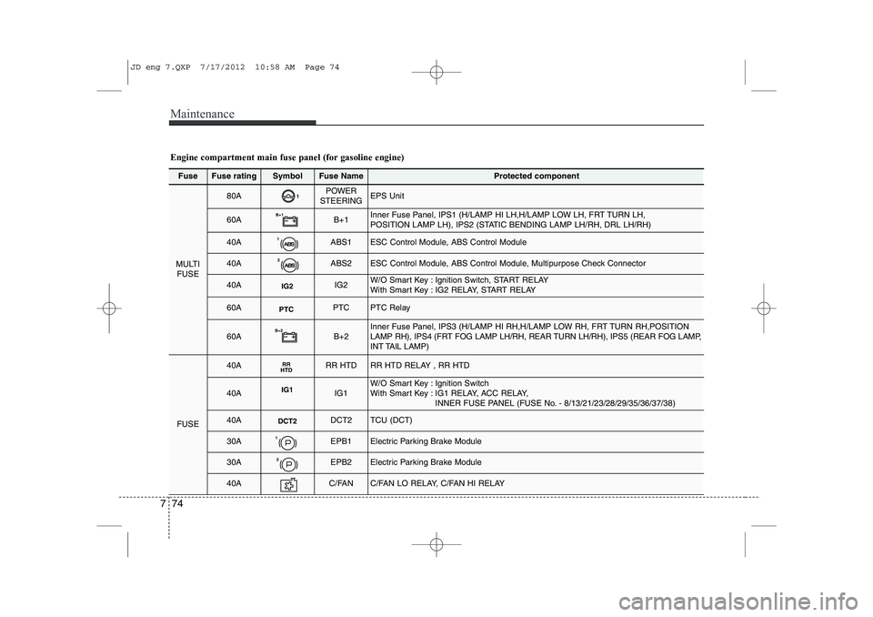
Fuse Fuse ratingSymbolFuse NameProtected component
MULTI
FUSE
80A1POWER
STEERINGEPS Unit
60AB+1B+1Inner Fuse Panel, IPS1 (H/LAMP HI LH,H/LAMP LOW LH, FRT TURN LH,
POSITION LAMP LH), IPS2 (STATIC BENDING LAMP LH/RH, DRL LH/RH)
40A1ABS1ESC Control Module, ABS Control Module
40A2ABS2ESC Control Module, ABS Control Module, Multipurpose Check Connector
40AIG2IG2W/O Smart Key : Ignition Switch, START RELAY
With Smart Key : IG2 RELAY, START RELAY
60APTCPTCPTC Relay
60AB+2B+2Inner Fuse Panel, IPS3 (H/LAMP HI RH,H/LAMP LOW RH, FRT TURN RH,POSITION
LAMP RH), IPS4 (FRT FOG LAMP LH/RH, REAR TURN LH/RH), IPS5 (REAR FOG LAMP,
INT TAIL LAMP)
FUSE
40ARR
HTDRR HTDRR HTD RELAY , RR HTD
40AIG1IG1W/O Smart Key : Ignition Switch
With Smart Key : IG1 RELAY, ACC RELAY,
INNER FUSE PANEL (FUSE No. - 8/13/21/23/28/29/35/36/37/38)
40ADCT2DCT2TCU (DCT)
30A1EPB1Electric Parking Brake Module
30A2EPB2Electric Parking Brake Module
40AC/FANC/FAN LO RELAY, C/FAN HI RELAY
Engine compartment main fuse panel (for gasoline engine)
JD eng 7.QXP 7/17/2012 10:58 AM Page 74
Page 530 of 1168

777
Maintenance
FuseFuse ratingSymbolFuse NameProtected component
MULTIFUSE
80A1POWER
STEERINGEPS Unit
60AB+1B+1Inner Fuse Panel, IPS1 (H/LAMP HI LH,H/LAMP LOW LH, FRT TURN LH, POSITION LAMP LH),
IPS2 (STATIC BENDING LAMP LH/RH, DRL LH/RH)
40A1ABS1ESC Control Module, ABS Control Module
40A2ABS2ESC Control Module, ABS Control Module, Multipurpose Check Connector
40AIG2IG2W/O Smart Key : Ignition Switch, START RELAYWith Smart Key : IG2 RELAY, START RELAY, INNER FUSE PANEL (Fuse No. - 14/24/22/15/10)
60AB+2B+2Inner Fuse Panel, IPS3 (H/LAMP HI RH,H/LAMP LOW RH, FRT TURN RH,
POSITION LAMP RH), IPS4 (FRT FOG LAMP LH/RH, REAR TURN LH/RH),
IPS5 (REAR FOG LAMP, INT TAIL LAMP)
FUSE
40ARR
HTDRR HTDRR HTD RELAY , RR HTD
40AIG1IG1W/O Smart Key : Ignition Switch
With Smart Key : IG1 RELAY, ACC RELAY, INNER FUSE PANEL ( Fuse No. - 38/36/21/37/
23/29/28, Fuse No. - 13/8/35)
30A1EPB1Electric Parking Brake Module
30A2EPB2Electric Parking Brake Module
50AC/FANC/FAN LO RELAY, C/FAN HI RELAY
15ADEICERICM Relay Box (Front Deicer Relay)
15ASTOP
LAMPSTOP LAMPStop Signal Electronic Relay, HAC RELAY
Engine compartment main fuse panel (for diesel engine)
JD eng 7.QXP 7/17/2012 10:58 AM Page 77
Page 534 of 1168

781
Maintenance
LIGHT BULBS
Use only the bulbs of the specifiedwattage.
✽✽ NOTICE
After driving in heavy rain or washing the vehicle, headlight and taillight lenses
could appear foggy. This condition is
caused by the temperature differencebetween the lamp inside and outside.
This is similar to the condensation on
your windows inside your vehicle during
rain and does not indicate a problem
with your vehicle. If the water leaks into
the lamp bulb circuitry, we recommendthat the system be checked by an
authorized Kia dealer.WARNING - Working on
the lights
Prior to working on the light, firmly
apply the parking brake, ensure
that the ignition switch is turned to
the “LOCK” position (smart key:turn off the engine) and turn off the
lights to avoid sudden movement
of the vehicle and burning your fin-
gers or getting an electric shock.
CAUTION
Be sure to replace the burned-out bulb with one of the same wattage rating. Otherwise, it may causedamage to the fuse or electricwiring system.
CAUTION
If you do not have necessary tools, the correct bulbs and the expertise,
we recommend that you consult anauthorized Kia dealer. In many cases, it is difficult to replace vehi-cle light bulbs because other parts
of the vehicle must be removedbefore you can get to the bulb. This is especially true if you have to
remove the headlight assembly to get to the bulb(s).
Removing/installing the headlightassembly can result in damage to the vehicle.
JD eng 7.QXP 7/17/2012 10:59 AM Page 81
Page 546 of 1168
793
Maintenance
Side repeater light bulb replace- ment
If the light bulb does not operate, we rec-
ommend that the system be checked by
an authorized Kia dealer.Rear combination light bulb replacement
(1) Rear turn signal light (2) Stop/tail light
(3) Back-up light (for 5Door)
(4) Tail light or stop/tail light (for LED type)
(5) Rear fog light (for 5Door)Rear fog light (Driver’s side) or
back-up light (Passenger’s side),
(for wagon) ❈
The actual rear combination lamp shape in
the vehicle may differ from illustration.
Outside light
Rear turn signal light and stop/tail light
1. Turn off the engine.
2. Open the tailgate.
3. Loosen the light assembly retaining
screws with a cross-tip screwdriver.
4. Remove the rear combination light assembly from the body of the vehicle.
OJD072045OJD072029
OJD072030
OJD072063
■5 Door
■Wagon
JD eng 7.QXP 7/21/2012 1:20 PM Page 93
Page 547 of 1168

Maintenance
94
7
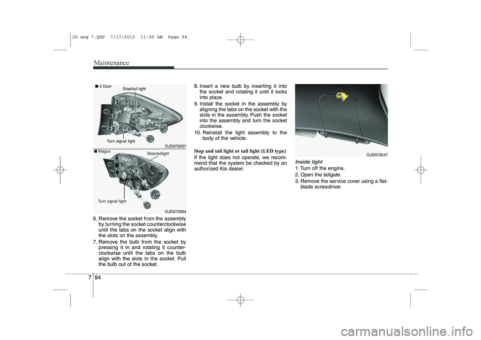
6. Remove the socket from the assembly
by turning the socket counterclockwise
until the tabs on the socket align with
the slots on the assembly.
7. Remove the bulb from the socket by pressing it in and rotating it counter-
clockwise until the tabs on the bulb
align with the slots in the socket. Pull
the bulb out of the socket. 8. Insert a new bulb by inserting it into
the socket and rotating it until it locks
into place.
9. Install the socket in the assembly by aligning the tabs on the socket with the
slots in the assembly. Push the socket
into the assembly and turn the socket
clockwise.
10. Reinstall the light assembly to the body of the vehicle.
Stop and tail light or tail light (LED type)
If the light does not operate, we recom-
mend that the system be checked by an
authorized Kia dealer.
Inside light
1. Turn off the engine.
2. Open the tailgate.
3. Remove the service cover using a flat- blade screwdriver.
OJD072047
OJD072057
OJD072064
■5 Door
■Wagon
Turn signal light
Stop/taillight
Turn signal light
Stop/tail light
JD eng 7.QXP 7/17/2012 11:00 AM Page 94
Page 549 of 1168

Maintenance
96
7
Back-up light and rear fog light (if equipped)
7. Remove the socket from the assembly
by turning the socket counterclockwise
until the tabs on the socket align with
the slots on the assembly.
8. Pull the bulb out of the socket.
9. Insert a new bulb into the socket.
10. Install the socket into the assembly by aligning the tabs on the socket
with the slots on the assembly and
turning the socket clockwise.
11. Reinstall the light assembly to the body of the vehicle
❈ Rear fog light is located only on the
driver’s side. (for wagon)
Tail light or stop and tail light (LED type)
If the light does not operate, we recom-
mend that the system be checked by an
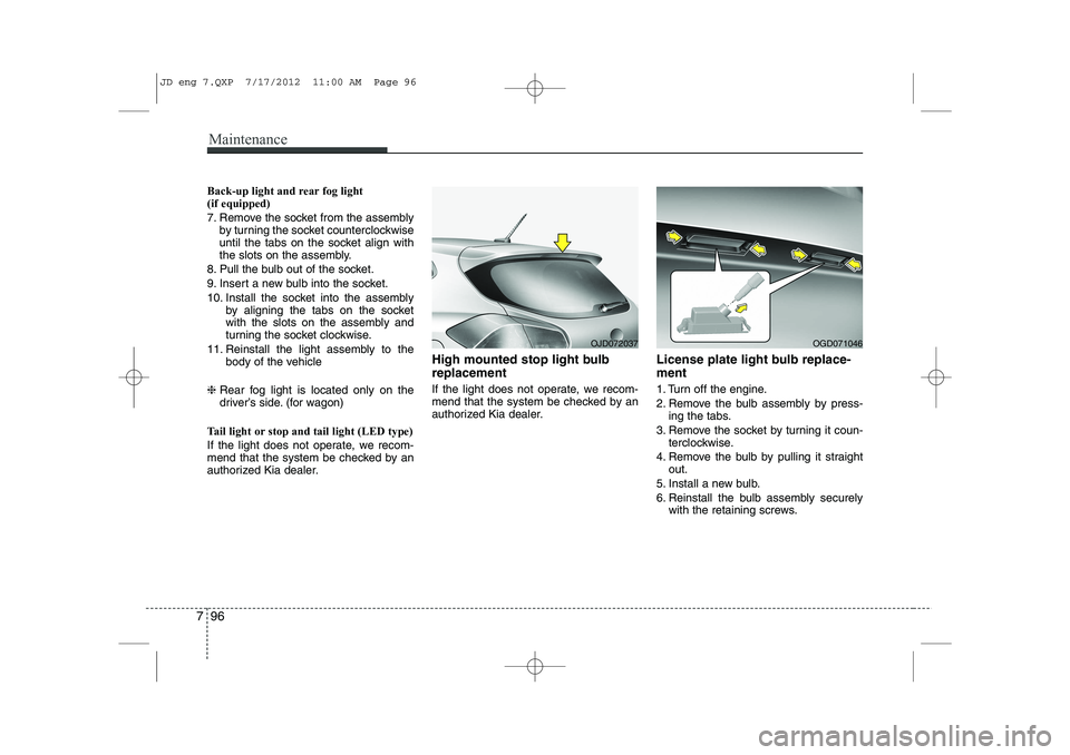
authorized Kia dealer. High mounted stop light bulb replacement
If the light does not operate, we recom-
mend that the system be checked by an
authorized Kia dealer.
License plate light bulb replace- ment
1. Turn off the engine.
2. Remove the bulb assembly by press-
ing the tabs.
3. Remove the socket by turning it coun- terclockwise.
4. Remove the bulb by pulling it straight out.
5. Install a new bulb.
6. Reinstall the bulb assembly securely with the retaining screws.
OJD072037OGD071046
JD eng 7.QXP 7/17/2012 11:00 AM Page 96
Page 558 of 1168

7 105
Maintenance
3. Exhaust emission control system
The Exhaust Emission Control System is
a highly effective system which controls
exhaust emissions while maintaining
good vehicle performance.
Vehicle modifications
This vehicle should not be modified.
Modification of your vehicle could affect
its performance, safety or durability and
may even violate governmental safety
and emissions regulations.
In addition, damage or performance
problems resulting from any modification
may not be covered under warranty.
If you use unauthorized electronic devices, it may cause the vehicle to
operate abnormally, wire damage, bat-
tery discharge or fire. For your safety,
do not use unauthorized electric
devices.
Engine exhaust gas precautions
(carbon monoxide)
Carbon monoxide can be present with other exhaust fumes. Therefore, if you
smell exhaust fumes of any kind inside
your vehicle, have it inspected and
repaired immediately. If you ever sus-
pect exhaust fumes are coming into
your vehicle, drive it only with all the
windows fully open. Have your vehicle
checked and repaired immediately. Do not operate the engine in confined
or closed areas (such as garages) any
more than what is necessary to move
the vehicle in or out of the area.
When the vehicle is stopped in an open area for more than a short time
with the engine running, adjust the
ventilation system (as needed) to draw
outside air into the vehicle.
Never sit in a parked or stopped vehi- cle for any extended time with the
engine running.
When the engine stalls or fails to start, excessive attempts to restart the
engine may cause damage to theemission control system.
WARNING - Exhaust
Engine exhaust gases contain car-
bon monoxide (CO). Though color-
less and odorless, it is dangerousand could be lethal if inhaled.
Follow the instructions following to
avoid CO poisoning.
JD eng 7.QXP 7/17/2012 11:01 AM Page 105