Page 1124 of 1168

1. Pull the wheel guard down by rotating the screws.
2. Reach your hand into the back of the front bumper.
3. Disconnect the power")
787
Maintenance
Front fog light, Daytime running light(if equipped)
1. Pull the wheel guard down by rotating the screws.
2. Reach your hand into the back of the front bumper.
3. Disconnect the power connector from the socket. 4. Remove the bulb-socket from the
housing by turning the socket counter
clockwise until the tabs on the socketalign with the slots on the housing.
5. Install the new bulb-socket into the housing by aligning the tabs on the
socket with the slots in the housing.
Push the socket into the housing and
turn the socket clockwise.
6. Connect the power connector to the socket. Headlight and front fog light aim-
ing (for Europe)Headlight aiming
Without AFLS
1. Inflate the tyres to the specified pres-
sure and remove any loads from the
vehicle except the driver, spare tyre,
and tools.
2. The vehicle should be placed on a flat floor.
3. Draw vertical lines (Vertical lines pass- ing through respective head lamp cen-
tres) and a horizontal line (Horizontalline passing through centre of headlamps) on the screen.
OJD072027OJD072050
■Fog light
■Fog light+DRL ■
DRL
OJD072061/OJD072059/OJD072060
JD RHD 7.QXP 7/21/2012 12:51 PM Page 87
Page 1125 of 1168

Maintenance
88
7
4. With the head lamp and battery in nor-
mal condition, aim the head lamps so
the brightest portion falls on the hori-
zontal and vertical lines.
5. To aim the low beam left or right, turn the driver (1) clockwise or counter-
clockwise. To aim the low beam up or
down, turn the driver (2) clockwise or
counterclockwise.
To aim the high beam up or down, turnthe driver (3) clockwise or counter-
clockwise. With AFLS
1. Turn off the engine
2. Turn the light switch to the low beam
position.
3. Position the tyres straight ahead with the steering wheel.
4. Turn on the engine.
5. Inflate the tyres to the specified pres- sure and remove any loads from the
vehicle except the driver, spare tyre,
and tools.
6. The vehicle should be placed on a flat floor.
7. Draw vertical lines (Vertical lines pass- ing through respective head lamp cen-
tres) and a horizontal line (Horizontalline passing through centre of headlamps) on the screen.
8. With the head lamp and battery in nor- mal condition, aim the head lamps so
the brightest portion falls on the hori-
zontal and vertical lines.
9. To aim the low beam left or right, turn the driver (1) clockwise or counter-
clockwise. To aim the low beam up or
down, turn the driver (2) clockwise or
counterclockwise. To aim the high
beam up or down, turn the driver (3)
clockwise or counterclockwise.
Front fog light aiming
The front fog lamp can be aimed as the same manner of the head lamps aiming.
With the front fog lamps and battery nor-
mal condition, aim the front fog lamps. To
aim the front fog lamp up or down, turn
the driver (1) clockwise or counterclock-
wise.
OJD072028
JD RHD 7.QXP 7/21/2012 12:51 PM Page 88
Page 1126 of 1168
789
Maintenance
Unit: mm (in)
Aiming point
OJD072051
< Ground Height >< Distance between lamps >
H1 : Height between the head lamp bulb center and ground (Low beam) H2 : Height between the head lamp bulb center and ground (High beam)H3 : Height between the fog lamp bulb center and groundW1 : Distance between the two head lamp bulbs centers (Low beam)W2 : Distance between the two head lamp bulbs centers (High beam)W3 : Distance between the two fog lamp bulbs centerscentre
centre
centre
centres
centres
centres
Vehicle
condition H1
H2
H3
W1
W2W3
Without AFLS With AFLS With DRLWithout
DRLWithoutAFLSWith AFLS With DRL Without
DRL
Without driver 689
(27.1) 687
(27.0)
646
(25.4) 340
(13.4)342
(13.5)
1,300
(51.2)1,299
(51.1)1,049
(41.3) 1,316
(51.8) 1,306
(51.4)
With driver 680
(26.8) 678
(26.7)
637
(25.1) 331
(13.0)333
(13.1)
JD RHD 7.QXP 7/21/2012 12:52 PM Page 89
Page 1127 of 1168
Maintenance
90
7
OMD051055L
Head lamp low beam (driver’s side)
1. Turn the low beam on without driver aboard.
2. The cut-off line should be projected in the cut-off line shown in the picture.
3. When aiming the low beam, vertical aiming should be adjusted after adjusting the horizontal aiming.
4. If head lamp levelling device is equipped, adjust the head lamp levelling device switch with 0 positions.
■
Based on 10m screen
JD RHD 7.QXP 7/21/2012 12:52 PM Page 90
Page 1128 of 1168
791
Maintenance
OMD051054L
Head lamp low beam (front passenger’s side)
1. Turn the low beam on without driver aboard.
2. The cut-off line should be projected in the cut-off line shown in the picture.
3. When aiming the low beam, vertical aiming should be adjusted after adjusting the horizontal aiming.
4. If head lamp levelling device is equipped, adjust the head lamp levelling device switch with 0 positions.
■
Based on 10m screen
JD RHD 7.QXP 7/21/2012 12:52 PM Page 91
Page 1129 of 1168
Maintenance
92
7
�
OGDE071056_JD
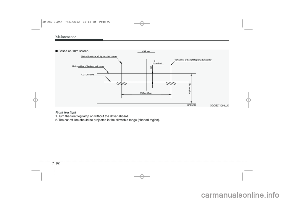
Front fog light
1. Turn the front fog lamp on without the driver aboard.
2. The cut-off line should be projected in the allowable range (shaded region).
■
Based on 10m screen
JD RHD 7.QXP 7/21/2012 12:52 PM Page 92
Page 1130 of 1168
793
Maintenance
Side repeater light bulb replace- ment
If the light bulb does not operate, we rec-
ommend that the system be checked by
an authorised Kia dealer.Rear combination light bulb replacement
(1) Rear turn signal light (2) Stop/tail light
(3) Back-up light (for 5Door)
(4) Tail light or stop/tail light (for LED type)
(5) Rear fog light (for 5Door)Rear fog light (Driver’s side) or
back-up light (Passenger’s side),
(for wagon) ❈
The actual rear combination lamp shape in
the vehicle may differ from illustration.
Outside light
Rear turn signal light and stop/tail light
1. Turn off the engine.
2. Open the tailgate.
3. Loosen the light assembly retaining
screws with a cross-tip screwdriver.
4. Remove the rear combination light assembly from the body of the vehicle.
OJD072045OJD072029/H
OJD072030
OJD072063
■5 Door
■Wagon
JD RHD 7.QXP 7/21/2012 12:52 PM Page 93
Page 1131 of 1168

Maintenance
94
7
6. Remove the socket from the assembly
by turning the socket counterclockwise
until the tabs on the socket align with
the slots on the assembly.
7. Remove the bulb from the socket by pressing it in and rotating it counter-
clockwise until the tabs on the bulb
align with the slots in the socket. Pull
the bulb out of the socket. 8. Insert a new bulb by inserting it into
the socket and rotating it until it locks
into place.
9. Install the socket in the assembly by aligning the tabs on the socket with the
slots in the assembly. Push the socket
into the assembly and turn the socket
clockwise.
10. Reinstall the light assembly to the body of the vehicle.
Stop and tail light or tail light (LED type)
If the light does not operate, we recom-
mend that the system be checked by an
authorised Kia dealer.
Inside light
1. Turn off the engine.
2. Open the tailgate.
3. Remove the service cover using a flat- blade screwdriver.
OJD072047
OJD072057
OJD072064
■5 Door
■Wagon
Turn signal light
Stop/taillight
Turn signal light
Stop/tail light
JD RHD 7.QXP 7/21/2012 12:52 PM Page 94

Aiming point
OJD072051
< Ground Height >< Distance between lamps >
H1 : Height between the head lamp bulb center and ground (Low beam) H2 : Height between the head lamp b")

1. Turn the low beam on without driver aboard.
2. The cut-off line should be projected in the cut-off line shown in the picture.
3. W")

1. Turn the low beam on without driver aboard.
2. The cut-off line should be projected in the cut-off line shown in the pictu")