2013 KIA CEED ESP
[x] Cancel search: ESPPage 1072 of 1168
735
Maintenance
ENGINE OIL
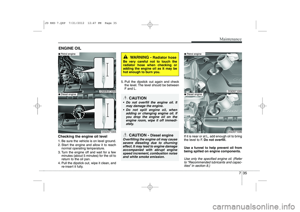
Checking the engine oil level
1. Be sure the vehicle is on level ground.
2. Start the engine and allow it to reach normal operating temperature.
3. Turn the engine off and wait for a few minutes (about 5 minutes) for the oil to
return to the oil pan.
4. Pull the dipstick out, wipe it clean, and re-insert it fully. 5. Pull the dipstick out again and check
the level. The level should be between F and L.
If it is near or at L, add enough oil to bring
the level to F.Do not overfill.
Use a funnel to help prevent oil frombeing spilled on engine components.
Use only the specified engine oil. (Refer to “Recommended lubricants and capac-
ities” in section 8.)
WARNING - Radiator hose
Be very careful not to touch the
radiator hose when checking or
adding the engine oil as it may be
hot enough to burn you.
CAUTION - Diesel engine
Overfilling the engine oil may cause
severe dieseling due to churningeffect. It may lead to engine damage
accompanied with abrupt enginespeed increment, combustion noise and white smoke emission.
CAUTION
Do not overfill the engine oil. It
may damage the engine.
Do not spill engine oil, when adding or changing engine oil. Ifyou drop the engine oil on theengine room, wipe it off immedi-
ately.
OGDE071003
■ Petrol engine
OGD071004
■Diesel engineOGD071005
■Petrol engine
OGD071006
■Diesel engine
JD RHD 7.QXP 7/21/2012 12:47 PM Page 35
Page 1097 of 1168
Maintenance
60
7
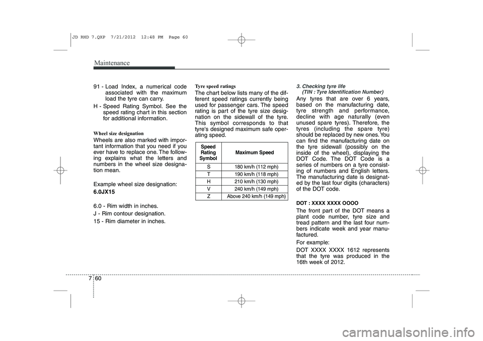
S 180 km/h (112 mph)
T 190 km/h (118 mph)
H 210 km/h (130 mph)
V 240 km/h (149 mph) Z Above 240 km/h (149 mph)
Maximum Speed
Speed
Rating
Symbol
91 - Load Index, a numerical code
associated with the maximum
load the tyre can carry.
H - Speed Rating Symbol. See the speed rating chart in this section
for additional information.
Wheel size designation
Wheels are also marked with impor-
tant information that you need if you
ever have to replace one. The follow-
ing explains what the letters and
numbers in the wheel size designa-tion mean.
Example wheel size designation: 6.0JX15
6.0 - Rim width in inches. J - Rim contour designation.
15 - Rim diameter in inches. Tyre speed ratings
The chart below lists many of the dif-
ferent speed ratings currently being
used for passenger cars. The speed
rating is part of the tyre size desig-
nation on the sidewall of the tyre.This symbol corresponds to that
tyre's designed maximum safe oper-ating speed.3. Checking tyre life
(TIN : Tyre Identification Number)
Any tyres that are over 6 years,
based on the manufacturing date,
tyre strength and performance,
decline with age naturally (even
unused spare tyres). Therefore, thetyres (including the spare tyre)
should be replaced by new ones. You
can find the manufacturing date on
the tyre sidewall (possibly on the
inside of the wheel), displaying the
DOT Code. The DOT Code is a
series of numbers on a tyre consist-
ing of numbers and English letters.
The manufacturing date is designat-
ed by the last four digits (characters)
of the DOT code.
DOT : XXXX XXXX OOOO
The front part of the DOT means a
plant code number, tyre size and
tread pattern and the last four num-
bers indicate week and year manu-
factured.
For example:
DOT XXXX XXXX 1612 represents
that the tyre was produced in the
16th week of 2012.
JD RHD 7.QXP 7/21/2012 12:48 PM Page 60
Page 1098 of 1168
761
Maintenance
4. Tyre ply composition and material
The number of layers or plies of rub-
ber-coated fabric are in the tyre. Tyre
manufacturers also must indicate the
materials in the tyre, which include
steel, nylon, polyester, and others.
The letter "R" means radial ply con-
struction; the letter "D" means diago-
nal or bias ply construction; and theletter "B" means belted-bias ply con-
struction.
5. Maximum permissible inflationpressure
This number is the greatest amount of air pressure that should be put in
the tyre. Do not exceed the maximum
permissible inflation pressure. Refer
to the Tyre and Loading Information
label for recommended inflation
pressure.
6. Maximum load rating
This number indicates the maximum
load in kilograms and pounds that
can be carried by the tyre. When
replacing the tyres on the vehicle,
always use a tyre that has the same
load rating as the factory installed
tyre.
7. Uniform tyre quality grading
Quality grades can be found where
applicable on the tyre sidewall
between tread shoulder and maxi-
mum section width.
For example:
TREADWEAR 200
TRACTION AA
TEMPERATURE A Tread wear
The tread wear grade is a compara-
tive rating based on the wear rate ofthe tyre when tested under controlled
conditions on a specified govern-
ment test course. For example, a tyre
graded 150 would wear one-and-a-
half times (1½) as well on the gov-
ernment course as a tyre graded100.
The relative performance of tyres depends upon the actual conditions
of their use, however, and may
depart significantly from the norm
because of variations in driving
habits, service practices and differ-
ences in road characteristics and cli-
mate.
These grades are molded on the
side-walls of passenger vehicle
tyres. The tyres available as standard
or optional equipment on your vehi-
cles may vary with respect to grade.
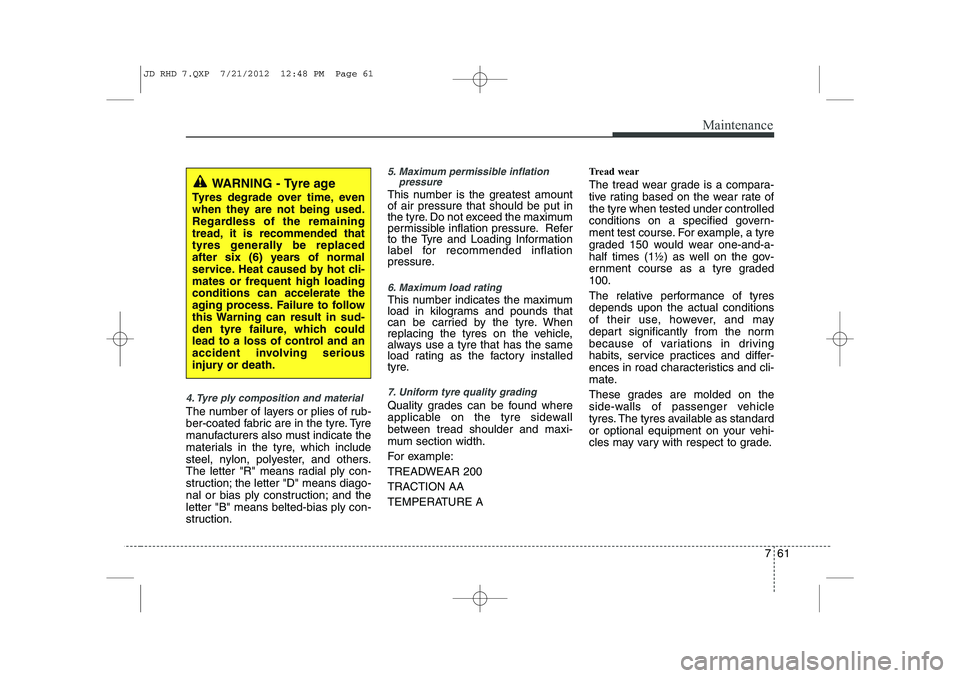
WARNING - Tyre age
Tyres degrade over time, even
when they are not being used.
Regardless of the remaining
tread, it is recommended that
tyres generally be replaced
after six (6) years of normal
service. Heat caused by hot cli-mates or frequent high loadingconditions can accelerate the
aging process. Failure to follow
this Warning can result in sud-
den tyre failure, which could
lead to a loss of control and an
accident involving serious
injury or death.
JD RHD 7.QXP 7/21/2012 12:48 PM Page 61
Page 1105 of 1168
Maintenance
68
7
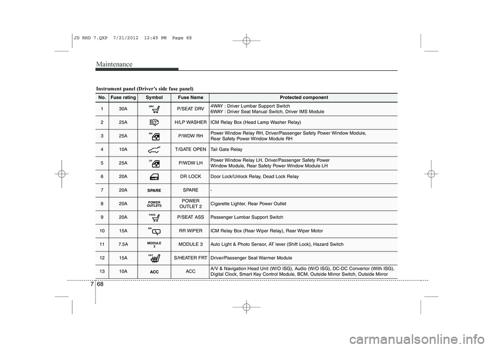
Instrument panel (Driver’s side fuse panel)
No.Fuse ratingSymbolFuse NameProtected component
130ADRVP/SEAT DRV4WAY : Driver Lumbar Support Switch
6WAY : Driver Seat Manual Switch, Driver IMS Module
225AH/LP WASHERICM Relay Box (Head Lamp Washer Relay)
325ARHP/WDW RHPower Window Relay RH, Driver/Passenger Safety Power Window Module,
Rear Safety Power Window Module RH
410AT/GATE OPENTail Gate Relay
525ALHP/WDW LHPower Window Relay LH, Driver/Passenger Safety Power
Window Module, Rear Safety Power Window Module LH
620ADR LOCKDoor Lock/Unlock Relay, Dead Lock Relay
720ASPARESPARE-
820APOWER
OUTLET2POWER
OUTLET 2Cigarette Lighter, Rear Power Outlet
920APASSP/SEAT ASSPassenger Lumbar Support Switch
1015ARRRR WIPERICM Relay Box (Rear Wiper Relay), Rear Wiper Motor
117.5AMODULE 3MODULE 3Auto Light & Photo Sensor, AT lever (Shift Lock), Hazard Switch
1215AFRTS/HEATER FRTDriver/Passenger Seat Warmer Module
1310AACCACCA/V & Navigation Head Unit (W/O ISG), Audio (W/O ISG), DC-DC Convertor (With ISG),
Digital Clock, Smart Key Control Module, BCM, Outside Mirror Switch, Outside Mirror
JD RHD 7.QXP 7/21/2012 12:49 PM Page 68
Page 1107 of 1168
Maintenance
70
7
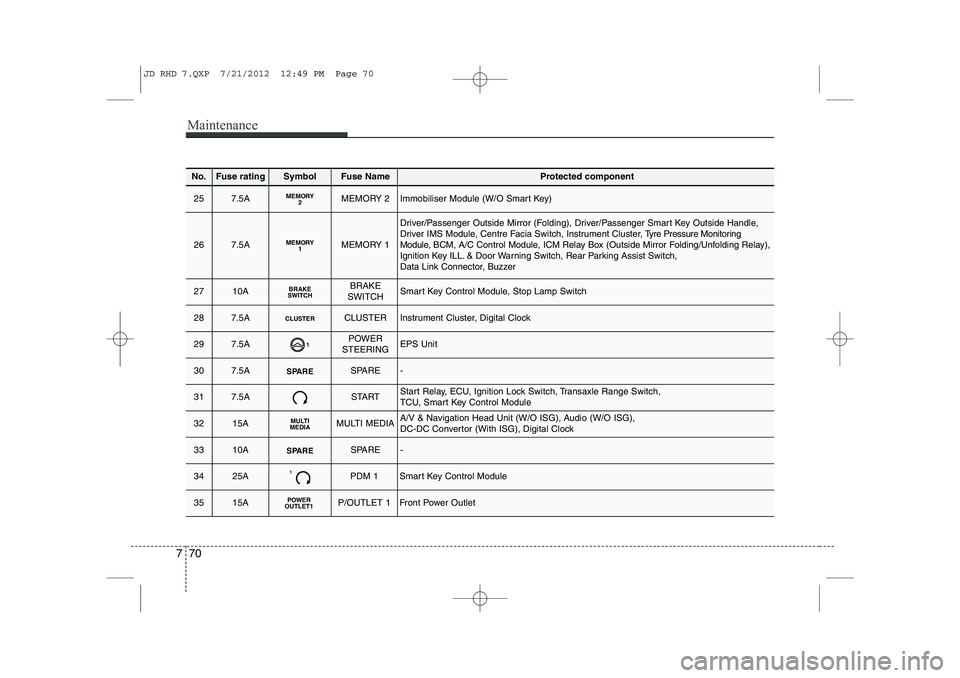
No.Fuse ratingSymbolFuse NameProtected component
257.5AMEMORY2MEMORY 2Immobiliser Module (W/O Smart Key)
267.5AMEMORY1MEMORY 1
Driver/Passenger Outside Mirror (Folding), Driver/Passenger Smart Key Outside Handle, Driver IMS Module, Centre Facia Switch, Instrument Cluster, T yre Pressure Monitoring
Module, BCM, A/C Control Module, ICM Relay Box (Outside Mirror Folding/Unfolding Relay),
Ignition Key ILL. & Door Warning Switch, Rear Parking Assist Switch,
Data Link Connector, Buzzer
2710ABRAKE
SWITCHBRAKE
SWITCHSmart Key Control Module, Stop Lamp Switch
287.5ACLUSTERCLUSTERInstrument Cluster, Digital Clock
297.5A1POWER
STEERINGEPS Unit
307.5ASPARESPARE-
317.5ASTARTStart Relay, ECU, Ignition Lock Switch, Transaxle Range Switch,
TCU, Smart Key Control Module
3215AMULTI
MEDIAMULTI MEDIAA/V & Navigation Head Unit (W/O ISG), Audio (W/O ISG),
DC-DC Convertor (With ISG), Digital Clock
3310ASPARESPARE-
3425A1PDM 1Smart Key Control Module
3515APOWER
OUTLET1P/OUTLET 1Front Power Outlet
JD RHD 7.QXP 7/21/2012 12:49 PM Page 70
Page 1116 of 1168
779
Maintenance
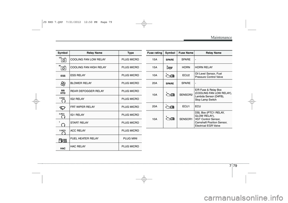
SymbolRelay NameType
LOCOOLING FAN LOW RELAYPLUG MICRO
HICOOLING FAN HIGH RELAYPLUG MICRO
ESSESS RELAYPLUG MICRO
BLOWER RELAYPLUG MICRO
RR
HTDREAR DEFOGGER RELAYPLUG MICRO
4 (IG2)IG2 RELAYPLUG MICRO
FRT WIPER RELAYPLUG MICRO
3 (IG1)IG1 RELAYPLUG MICRO
1START RELAYPLUG MICRO
2 (ACC)ACC RELAYPLUG MICRO
FUEL HEATER RELAYPLUG MINI
HACHAC RELAYPLUG MICRO
Fuse ratingSymbolFuse NameRelay Name
15ASPARESPARE-
15AHORNHORN RELAY
10A2ECU2Oil Level Sensor, Fuel
Pressure Control Valve
20ASPARESPARE-
10A9SENSOR2
E/R Fuse & Relay Box
(COOLING FAN LOW RELAY),Lambda Sensor (D4FB), Stop Lamp Switch
20A1ECU1ECU
10A8SENSOR1
DSL Box (PTC1 RELAY,
GLOW RELAY),
VGT Control Sensor,
Camshaft Position Sensor,
Electrical EGR Valve
JD RHD 7.QXP 7/21/2012 12:50 PM Page 79
Page 1118 of 1168
781
Maintenance
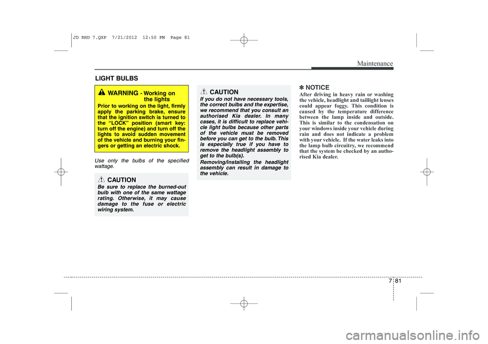
LIGHT BULBS
Use only the bulbs of the specifiedwattage.
✽✽ NOTICE
After driving in heavy rain or washing the vehicle, headlight and taillight lenses
could appear foggy. This condition is
caused by the temperature differencebetween the lamp inside and outside.
This is similar to the condensation on
your windows inside your vehicle during
rain and does not indicate a problem
with your vehicle. If the water leaks into
the lamp bulb circuitry, we recommendthat the system be checked by an autho-
rised Kia dealer.WARNING - Working on
the lights
Prior to working on the light, firmly
apply the parking brake, ensure
that the ignition switch is turned to
the “LOCK” position (smart key:turn off the engine) and turn off the
lights to avoid sudden movement
of the vehicle and burning your fin-
gers or getting an electric shock.
CAUTION
Be sure to replace the burned-out bulb with one of the same wattage rating. Otherwise, it may causedamage to the fuse or electricwiring system.
CAUTION
If you do not have necessary tools, the correct bulbs and the expertise,
we recommend that you consult anauthorised Kia dealer. In many cases, it is difficult to replace vehi-cle light bulbs because other parts
of the vehicle must be removedbefore you can get to the bulb. This is especially true if you have to
remove the headlight assembly to get to the bulb(s).
Removing/installing the headlightassembly can result in damage to the vehicle.
JD RHD 7.QXP 7/21/2012 12:50 PM Page 81
Page 1124 of 1168
787
Maintenance
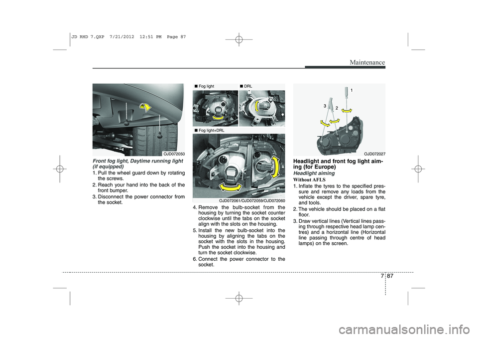
Front fog light, Daytime running light(if equipped)
1. Pull the wheel guard down by rotating the screws.
2. Reach your hand into the back of the front bumper.
3. Disconnect the power connector from the socket. 4. Remove the bulb-socket from the
housing by turning the socket counter
clockwise until the tabs on the socketalign with the slots on the housing.
5. Install the new bulb-socket into the housing by aligning the tabs on the
socket with the slots in the housing.
Push the socket into the housing and
turn the socket clockwise.
6. Connect the power connector to the socket. Headlight and front fog light aim-
ing (for Europe)Headlight aiming
Without AFLS
1. Inflate the tyres to the specified pres-
sure and remove any loads from the
vehicle except the driver, spare tyre,
and tools.
2. The vehicle should be placed on a flat floor.
3. Draw vertical lines (Vertical lines pass- ing through respective head lamp cen-
tres) and a horizontal line (Horizontalline passing through centre of headlamps) on the screen.
OJD072027OJD072050
■Fog light
■Fog light+DRL ■
DRL
OJD072061/OJD072059/OJD072060
JD RHD 7.QXP 7/21/2012 12:51 PM Page 87