Page 403 of 655

• Most of the time, when in Automatic Operation, you
can temporarily put the system into Recirculation
mode by pressing the Recirculation button. However,
under certain conditions, while in Automatic mode,
the system is blowing air out the defrost vents. When
these conditions are present, and the Recirculation
button is pressed, the indicator will flash and then turn
off. This tells you that you are unable to go into
Recirculation mode at this time. If you would like the
system to go into Recirculation mode, you must first
move the Mode knob to Panel, Bi-Level and then press
the Recirculation button. This feature reduces the
possibility of window fogging.
Operating Tips
NOTE: Refer to the chart at the end of this section for
suggested control settings for various weather conditions. Summer Operation
The engine cooling system in air-conditioned vehicles
must be protected with a high-quality antifreeze coolant
to provide proper corrosion protection and to protect
against engine overheating. A solution of 50% ethylene
glycol antifreeze coolant and 50% water is recommended.
Refer to “Maintenance Procedures” in “Maintaining Your
Vehicle” for proper coolant selection.
Winter Operation
Use of the air Recirculation mode during winter months is
not recommended because it may cause window fogging.
Vacation Storage
Anytime you store your vehicle, or keep it out of service
(i.e., vacation) for two weeks or more, run the air
conditioning system at idle for about five minutes in the
fresh air and high blower settings. This will ensure
adequate system lubrication to minimize the possibility
of compressor damage when the system is started again. 4 UNDERSTANDING YOUR INSTRUMENT PANEL 401
Page 404 of 655

Window Fogging
Interior fogging on the windshield can be quickly re-
moved by turning the mode selector to Defrost. The
Defrost/Floor mode can be used to maintain a clear
windshield and provide sufficient heating. If side win-
dow fogging becomes a problem, increase blower speed.
Vehicle windows tend to fog on the inside in mild but
rainy or humid weather.
NOTE: Recirculate without A/C should not be used for
long periods as fogging may occur.
Side Window Demisters
A side window demister outlet is located at each end of
the instrument panel. These non-adjustable outlets direct
air toward the side windows when the system is in the
Floor, Mix, or Defrost mode. The air is directed at the area
of the windows through which you view the outside
mirrors. Outside Air Intake
Make sure the air intake, located directly in front of the
windshield, is free of obstructions such as leaves. Leaves
collected in the air intake may reduce airflow, and if they
enter the plenum, they could plug the water drains. In
winter months, make sure the air intake is clear of ice,
slush, and snow.
A/C Air Filter — If Equipped
The A/C Filter prevents most dust and pollen from
entering the cabin. The filter acts on air coming from
outside the vehicle and recirculated air within the pas-
senger compartment. Refer to “Maintenance Procedures”
in “Maintaining Your Vehicle” for A/C Air Filter service
information or see your authorized dealer for service.
Refer to “Maintenance Schedules” for filter service inter-
vals.402 UNDERSTANDING YOUR INSTRUMENT PANEL
Page 405 of 655
Control Setting Suggestions For Various Weather Conditions
4 UNDERSTANDING YOUR INSTRUMENT PANEL 403
Page 435 of 655
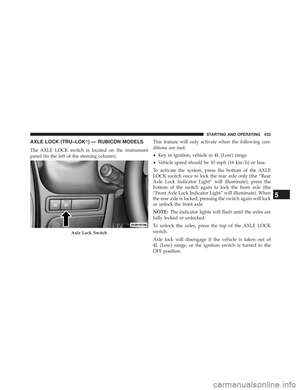
AXLE LOCK (TRU–LOK � ) — RUBICON MODELS
The AXLE LOCK switch is located on the instrument
panel (to the left of the steering column). This feature will only activate when the following con-
ditions are met:
• Key in ignition, vehicle in 4L (Low) range.
• Vehicle speed should be 10 mph (16 km/h) or less.
To activate the system, press the bottom of the AXLE
LOCK switch once to lock the rear axle only (the “Rear
Axle Lock Indicator Light” will illuminate), press the
bottom of the switch again to lock the front axle (the
“Front Axle Lock Indicator Light” will illuminate). When
the rear axle is locked, pressing the switch again will lock
or unlock the front axle.
NOTE: The indicator lights will flash until the axles are
fully locked or unlocked.
To unlock the axles, press the top of the AXLE LOCK
switch.
Axle lock will disengage if the vehicle is taken out of
4L (Low) range, or the ignition switch is turned to the
OFF position.Axle Lock Switch
5 STARTING AND OPERATING 433
Page 436 of 655
ELECTRONIC SWAY BAR DISCONNECT —
IF EQUIPPED
Your vehicle may be equipped with an electronic discon-
necting stabilizer/sway bar. This system allows greater
front suspension travel in off-road situations.
This system is controlled by the SWAY BAR switch
located on the instrument panel (to the left of the steering
column).
Press the SWAY BAR switch to activate the system. Press
the switch again to deactivate the system. The “Sway Bar
Indicator Light” (located in the instrument cluster) will
illuminate when the bar is disconnected. The “Sway Bar
Indicator Light” will flash during activation transition, or
when activation conditions are not met. The stabilizer/ Sway Bar Switch434 STARTING AND OPERATING
Page 504 of 655
Tire Pressure Monitoring Low Pressure Warnings
The Tire Pressure Monitoring Telltale Light will
illuminate in the instrument cluster, and an au-
dible chime will be activated, when one or more of
the four active road tire pressures are low. In addition, the
EVIC will display a “LOW TIRE PRESSURE” message for
a minimum of five seconds, and a graphic display of the
pressure value(s) with the low tire(s) “flashing.” Refer to
“Electronic Vehicle Information Center (EVIC)” in “Un-
derstanding Your Instrument Panel” for further
information. NOTE: Your system can be set to display pressure units
in PSI, kPa, or BAR.
Should a low tire condition occur on any of the four
active road tire(s), you should stop as soon as possible,
and inflate the low tire(s) that is “flashing” on the graphic
display to the vehicle’s recommended cold tire pressure.502 STARTING AND OPERATING
Page 540 of 655

HAZARD WARNING FLASHERS
The Hazard Warning flasher switch is located on the
instrument panel below the climate controls.
Press the switch to turn on the Hazard Warning
flasher. When the switch is activated, all direc-
tional turn signals will flash on and off to warn oncoming
traffic of an emergency. Press the switch a second time to
turn off the Hazard Warning flashers.
This is an emergency warning system and it should not
be used when the vehicle is in motion. Use it when your
vehicle is disabled and it is creating a safety hazard for
other motorists. When you must leave the vehicle to seek assistance, the
Hazard Warning flashers will continue to operate even
though the ignition is placed in the OFF position.
NOTE: With extended use the Hazard Warning flashers
may wear down your battery.
IF YOUR ENGINE OVERHEATS
In any of the following situations, you can reduce the
potential for overheating by taking the appropriate action.
• On the highways — slow down.
• In city traffic — while stopped, shift transmission into
NEUTRAL, but do not increase engine idle speed.538 WHAT TO DO IN EMERGENCIES
Page 616 of 655

MAINTENANCE SCHEDULE
Your vehicle is equipped with an automatic oil change
indicator system. The oil change indicator system will
remind you that it is time to take your vehicle in for
scheduled maintenance.
Based on engine operation conditions, the oil change
indicator message will illuminate. This means that service
is required for your vehicle. Operating conditions such as
frequent short-trips, trailer tow, extremely hot or cold
ambient temperatures, and E85 fuel usage will influence
when the “Change Oil” or “Oil Change Required” message
is displayed. Severe Operating Conditions can cause the
change oil message to illuminate as early as 3,500 miles
(5,600 km) since last reset. Have your vehicle serviced as
soon as possible, within the next 500 miles (805 km).
On Electronic Vehicle Information Center (EVIC) equipped
vehicles, “Oil Change Required” will be displayed in the
EVIC and a single chime will sound, indicating that an oil
change is necessary. On Non-EVIC equipped vehicles, “Change Oil” will flash
in the instrument cluster odometer and a single chime
will sound, indicating that an oil change is necessary.
Your authorized dealer will reset the oil change indicator
message after completing the scheduled oil change. If a
scheduled oil change is performed by someone other than
your authorized dealer, the message can be reset by refer-
ring to the steps described under “Electronic Vehicle Infor-
mation Center (EVIC)/Oil Change Required” in “Under-
standing Your Instrument Panel” or under “Instrument
Cluster Description/Odometer/Trip Odometer” in “Under-
standing Your Instrument Panel” for further information.
NOTE: Under no circumstances should oil change inter-
vals exceed 10,000 miles (16,000 km) or twelve months,
whichever comes first.
8 M
A
I
N
T
E
N
A
N
C
E
S
C
H
E
D
U
L
E
S 614 MAINTENANCE SCHEDULES